Construction method and double-layer formwork structure for cast-in-situ slope roof

A double-layer formwork and construction method technology, which is applied in the direction of formwork/formwork/work frame, joints of formwork/formwork/work frame, roof, etc., can solve the problem that the compactness of concrete pouring is difficult to control and the construction quality is difficult to achieve The expected effect, easy seepage and leakage of concrete structure construction, to achieve the effect of reducing the loss of concrete materials, avoiding hidden dangers of leakage, and high cross-sectional dimension accuracy

Inactive Publication Date: 2017-02-22
CHINA THIRD METALLURGICAL GRP
View PDF5 Cites 15 Cited by
  • Summary
  • Abstract
  • Description
  • Claims
  • Application Information

AI Technical Summary

Problems solved by technology

However, due to the improper selection of construction methods in the construction of the slope roof, it is easy to cause the concrete pouring to be not dense, and it is easy to cause leakage
[0003] The traditional sloping roof refers to the sloping roof with a slope of 25° to 60°. During construction, the formwork on the bottom surface of the slope is usually installed or a layer of steel wire mesh is added on the reinforcement surface before pouring and compaction. However, when the slope is steep, vibration Concrete slipping and segregation are often caused during the pounding process, so that the concrete can only be formed naturally on the slope surface in a state of unconstrained sliding, so it is difficult to control the compactness of concrete pouring, and the construction quality is difficult to achieve the expected effect, which leaves a lot of space for the construction of concrete structures. Hidden dangers and common quality problems that are easy to seep and leak

Method used


Image

  • Construction method and double-layer formwork structure for cast-in-situ slope roof
  • Construction method and double-layer formwork structure for cast-in-situ slope roof
  • Construction method and double-layer formwork structure for cast-in-situ slope roof

Examples


Embodiment Construction

[0034] The specific embodiment of the present invention will be further described below in conjunction with accompanying drawing:

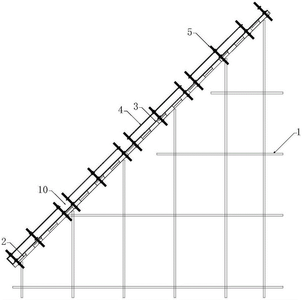
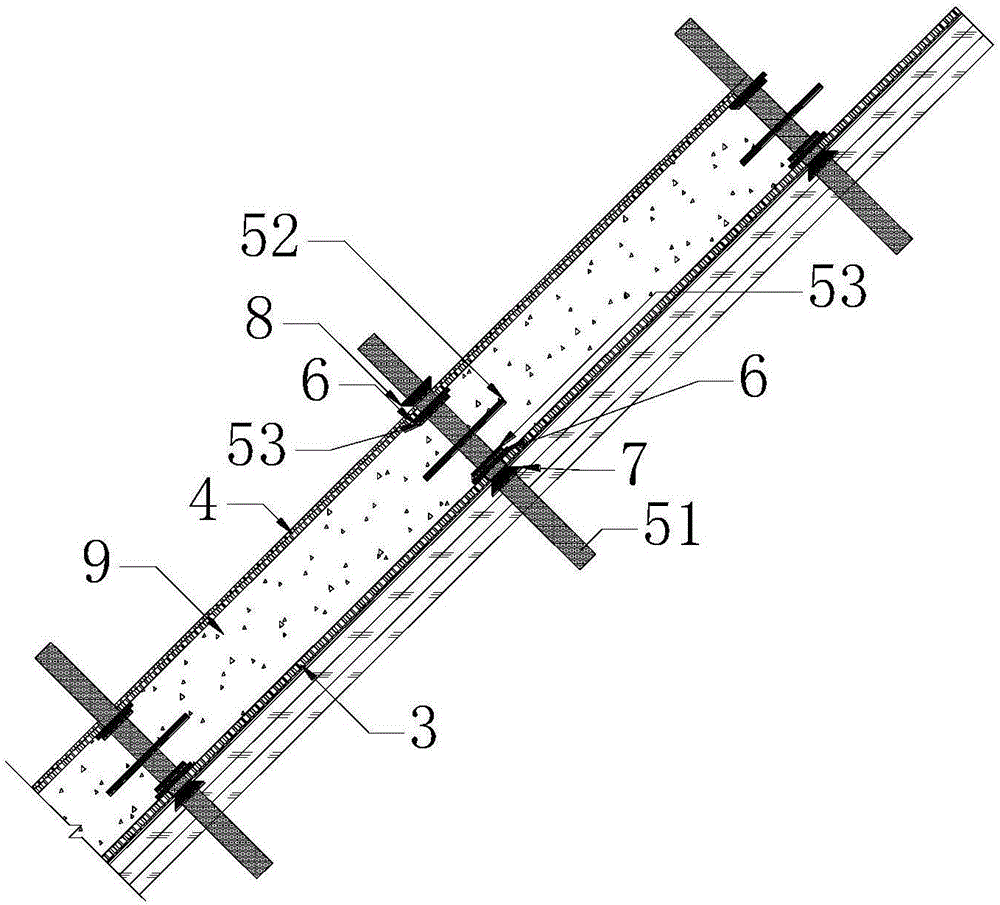
[0035] Such as figure 1 , figure 2 As shown, a double-layer formwork structure for cast-in-place sloping roofs according to the present invention includes a support rod system 1, a formwork keel 2, a bottom formwork 3, a surface formwork 4, and a pair of pull positioning water-stop bolts 5; the formwork keel 2 It is arranged obliquely along the height of the roof, and its inclination is consistent with the slope of the sloping roof, and its bottom is supported and fixed by the support rod system 1; The bottom formwork 3 is arranged in parallel, and the distance between the two is equal to the thickness of the concrete pouring layer 9 of the sloping roof; The outer sides of the formwork 4 are locked and fixed by the bottom nut 7 and the top nut 8 respectively; the surface formwork 4 is composed of a plurality of segmented surface formworks arran...


PUM


Abstract

The invention relates to a construction method and a double-layer formwork structure for a cast-in-situ slope roof. The double-layer formwork structure comprises a supporting rod system, a formwork keel, a bottom formwork, a surface formwork and counter-pull positioning waterproof bolts. The bottom of the formwork keel is fixedly supported by the supporting rod system; the bottom formwork is laid on the upper surface of the formwork keel, the surface formwork is parallel to the bottom formwork, and a distance between the surface formwork and the bottom formwork is equal to the thickness of a concrete pouring layer of the slope roof; the bottom formwork and the surface formwork are positioned through the counter-pull positioning waterproof bolts; the surface formwork is formed by a plurality of segmented surface formworks at intervals, and a trough formed by ends of the adjacent segmented surface formworks and the bottom formwork serves as a vibration tamping trough for segmented pouring of concrete. By adoption of the double-layer formwork structure and a segmented concrete pouring and vibration tamping method, the problem of proneness to slipping of concrete in construction of the slope roof is solved, structural compactness, high section size precision and high surface quality of concrete after pouring and tamping are achieved, and the construction method is simple and feasible.

Description

technical field [0001] The invention relates to the technical field of cast-in-place sloping roof construction, in particular to a double-layer formwork structure for a cast-in-situ sloping roof and a construction method for a sloping roof. Background technique [0002] With the development of the construction industry and the diversification of people's living needs, in recent years, many novel and unique sloping roof structures have appeared in architectural design. However, due to the improper selection of construction methods during the construction of the slope roof, it is easy to cause the concrete pouring to be not dense, and it is easy to cause leakage. [0003] The traditional sloping roof refers to the sloping roof with a slope of 25° to 60°. During construction, the formwork on the bottom surface of the slope is usually installed or a layer of steel wire mesh is added on the reinforcement surface before pouring and compaction. However, when the slope is steep, vib...

Claims


Application Information

Patent Timeline
Patent Type & Authority Applications(China)
IPC IPC(8): E04G11/38E04G17/065E04B7/02
CPCE04G11/38E04B7/02E04G17/0655
Inventor 张睿王卫东白威
Owner CHINA THIRD METALLURGICAL GRP
Why Eureka
Try Eureka