Molecule activated device

An activator and molecular technology, applied in the direction of machines/engines, engine components, charging systems, etc., can solve problems such as carbon deposits, insufficient power, engine fuel consumption, shortened engine life, etc., achieve stable reaction effects, and increase purchase intentions , the effect of reducing air pollution

Inactive Publication Date: 2017-02-22
张元正
View PDF6 Cites 0 Cited by
  • Summary
  • Abstract
  • Description
  • Claims
  • Application Information

AI Technical Summary

Problems solved by technology

[0003] Most of the fuel oil has the problem of whether it can be completely burned. Therefore, if the fuel oil is incompletely burned, it will not only emit carbon monoxide and hydrocarbons to cause environmental pollution, but also paraffin, colloid and other substances that cannot be completely burned in the fuel oil. It will form colloidal carbon residues inside the internal combustion engine, and if it accumulates too much, it will cause problems such as fuel consumption, carbon deposits, and insufficient power of the engine.
[0004] The reason for the incomplete combustion of fuel oil is that the molecular structure of fuel oil is large and the arrangement is disordered. When it is mixed with air molecules for ignition or compression explosion combustion, it will not be able to burn completely, and finally it will be discharged into the atmosphere with exhaust gas. Therefore, the current industry That is to widely implement various methods that can improve the combustion efficiency of fuel
[0005] One of them is to add a combustion aid to the fuel, or use a carbon remover to directly affect the fuel, but the above method will not only cost a lot, increase waste, but also cause users to have doubts about shortening the life of the engine. The other is to wrap the fuel economizer with far-infrared radiating material on the oil pipe, but the above method is not only troublesome in assembly, but also requires some professional tools and professional personnel to operate, which is inconvenient and expensive

Method used


Image

  • Molecule activated device
  • Molecule activated device
  • Molecule activated device

Examples


Embodiment Construction

[0036] In order to make the object, technical solution and advantages of the present invention clearer, the present invention will be described in detail below with reference to the accompanying drawings and specific embodiments.

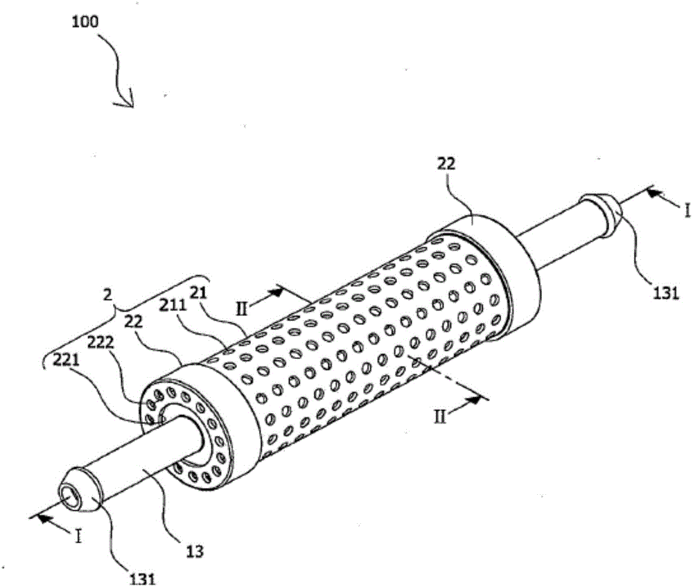
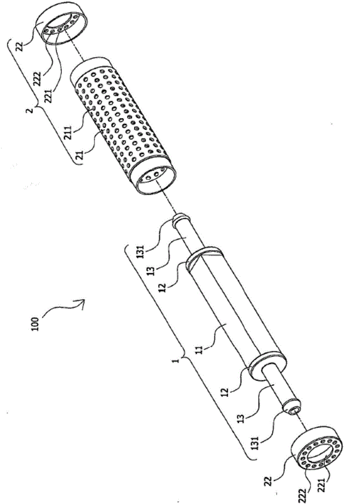
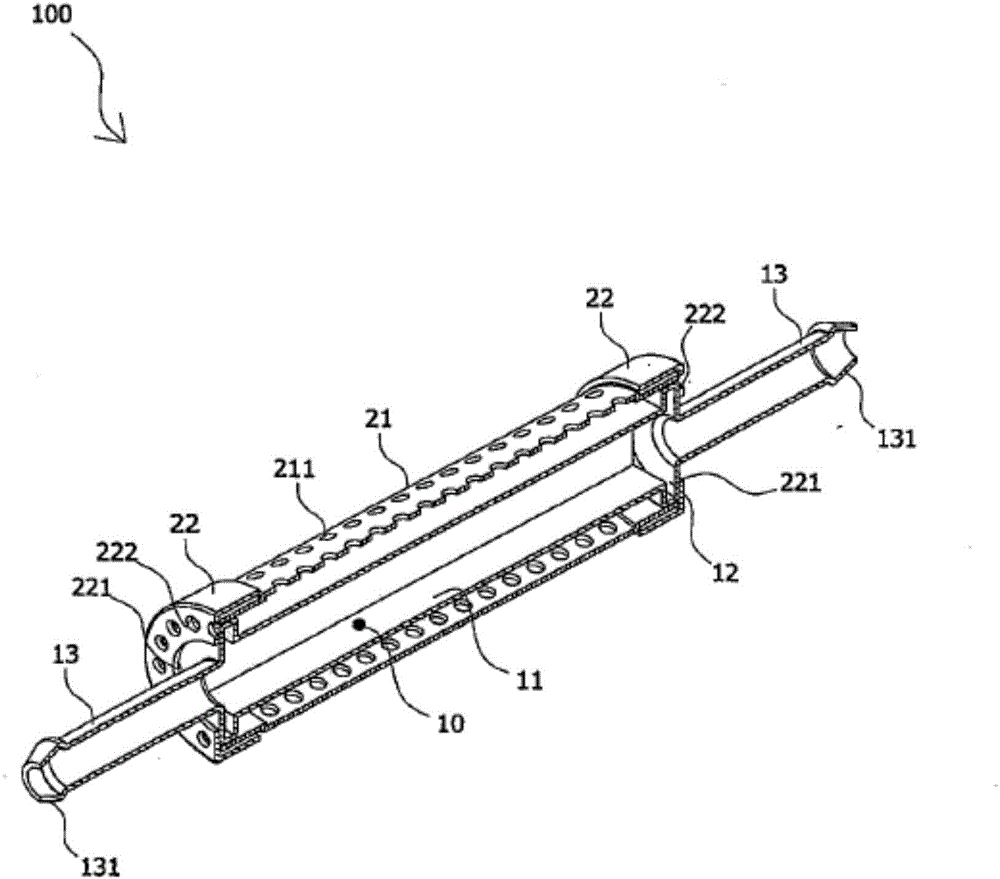
[0037] Such as Figure 1 ~ Figure 4 Shown in the figure is a molecular activator according to an embodiment of the present invention, wherein the molecular activator 100 includes a fuel pipeline 1 and an outer casing 2; the fuel pipeline 1 is It consists of a square tube 11, two round baffles 12 covering both ends of the square tube 11, and two communicating tubes 13 respectively located in the center of the two round baffles 12, and the square tube 11 has one and the two The fuel space 10 connected by the connecting pipe 13; the outer casing 2, which is arranged outside the fuel pipeline 1, and the outer casing 2 includes a round shape located outside the square pipe 11 and having a plurality of first holes 211 tube 21 ; and two round caps 22 resp...


PUM


Abstract

The invention provides a molecule activated device installed in a traffic tool. The device comprises a combustion oil pipe and a housing. The combustion oil pipe is formed by a square tube, two round baffle pieces shielding two ends of the square tube respectively, and two connecting tubes at the center of the two round baffle pieces respectively. The square tube comprises combustion oil space communicating with the two connecting tubes. The housing is arranged on the outer side of the combustion oil pipe. The housing comprises a round tube which is outside the square tube and has a plurality of first holes, and two round covers each of which is corresponding to an end of the round tube and has a through hole passing through one of the two connecting tubes. The device can help combustion oil achieve complete burning to save oil and improve power effect. Besides, the device can be used in combination with various traffic tools, so that an internal combustion engine is not damaged by accumulated carbon. The discharged exhaust gas meets the national standards, and air pollution is reduced, so that purchasing wills of consumers are improved, and thus the device meets the demands of the market.

Description

technical field [0001] The invention relates to the technical field of power devices, in particular to a molecular activator which can be installed in vehicles. Background technique [0002] Most of today's vehicles must use fuel oil as the main power source. After the fuel oil enters the internal combustion engine of the vehicle and atomizes the mixture, it generates heat to expand the gas when heated, and converts it into mechanical energy through mechanical devices to do work externally. Internal combustion engines have a very wide range of applications, such as aviation, vehicle, ship and other engines are basically internal combustion engines, the most common examples of which are automotive gasoline engines and diesel engines. [0003] Most of the fuel oil has the problem of whether it can be completely burned. Therefore, if the fuel oil is incompletely burned, it will not only emit carbon monoxide and hydrocarbons to cause environmental pollution, but also paraffin, c...

Claims


Application Information

Patent Timeline
Patent Type & Authority Applications(China)
IPC IPC(8): F02M27/00
CPCF02M27/00
Inventor 张元正
Owner 张元正
Why Eureka
Try Eureka