Rotary air compressor head

An air compressor and rotary technology, which is applied in the field of air compressor manufacturing, can solve the problems of reduced sealing effect between the sliding vane and the cylinder body, reduced air compression efficiency of the air compressor, and shortened service life, etc., so as to improve the service life , to ensure compression efficiency and reduce costs

Inactive Publication Date: 2019-08-09
台州阳光电机泵业有限公司
View PDF17 Cites 0 Cited by
  • Summary
  • Abstract
  • Description
  • Claims
  • Application Information

AI Technical Summary

Problems solved by technology

[0002] The air compressor is an important general-purpose compression machine. The current rolling piston type compression machine (application number is 200410053347.9) will generate a large friction force between the piston and the sliding plate during operation, and the current flat The dynamic rotary compression device (application number 200820121680.2) avoids the large friction at the end of the slide to prevent wear and improve the service life, but in these compression machines, the friction generated between the side wall of the slide and the cylinder cannot be avoided. After a long time of use, the side wall of the slide plate wears more and the sealing effect between the slide plate and the cylinder body is greatly reduced, thereby reducing the efficiency of the air compressor to compress air, and reducing the friction of the slide plate side wall is the rolling piston. It is a key technical problem that people in the field of compression machinery urgently need to solve. At present, a better solution is to use self-lubricating and wear-resistant materials to improve the service life, but the sliding plate will still wear, and when the compression efficiency is too low, people It is necessary to disassemble the machine head to replace the sliding vane, and frequent disassembly of the air compressor will shorten the service life and increase the maintenance cost in the later period

Method used


Image

  • Rotary air compressor head
  • Rotary air compressor head

Examples


Embodiment Construction

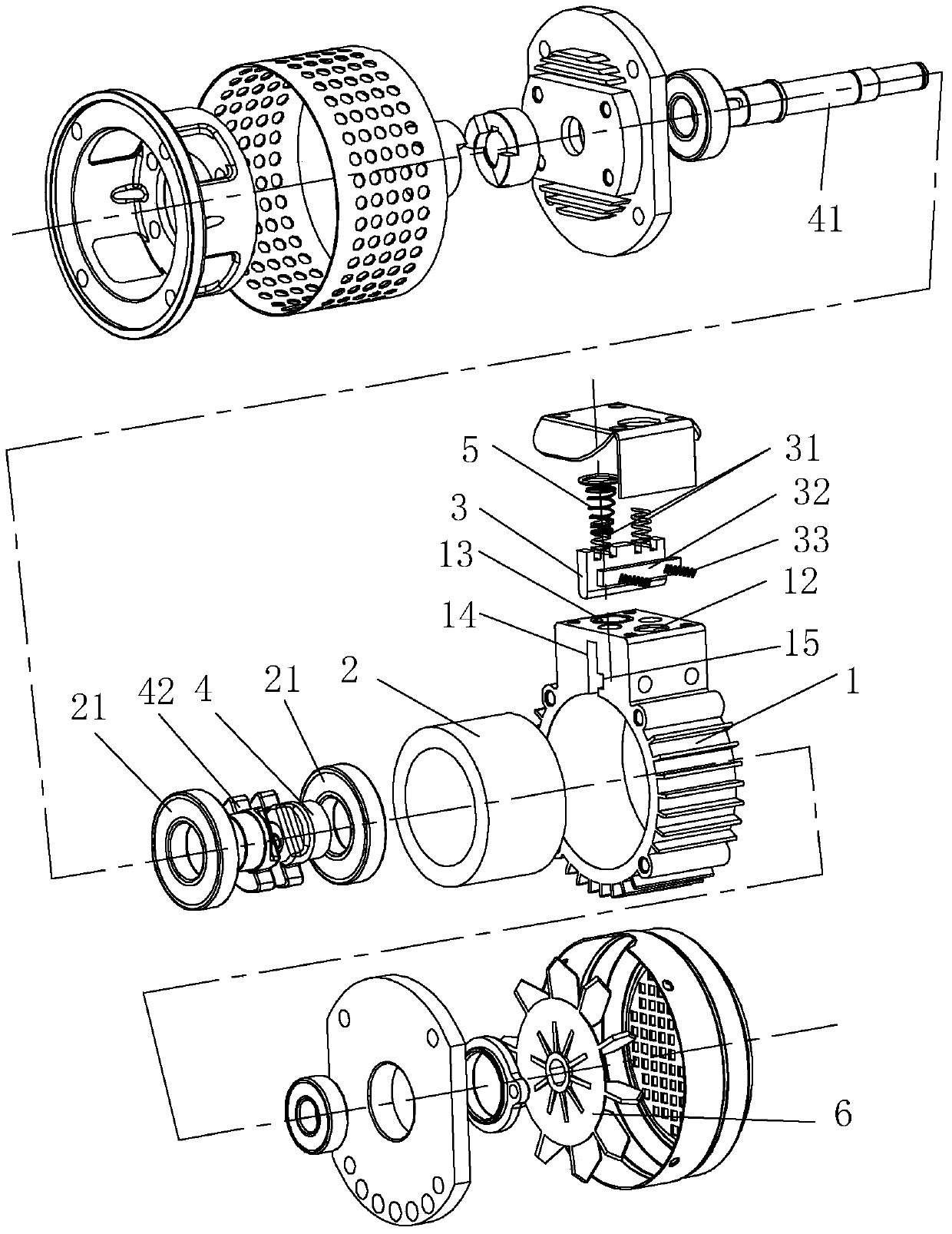
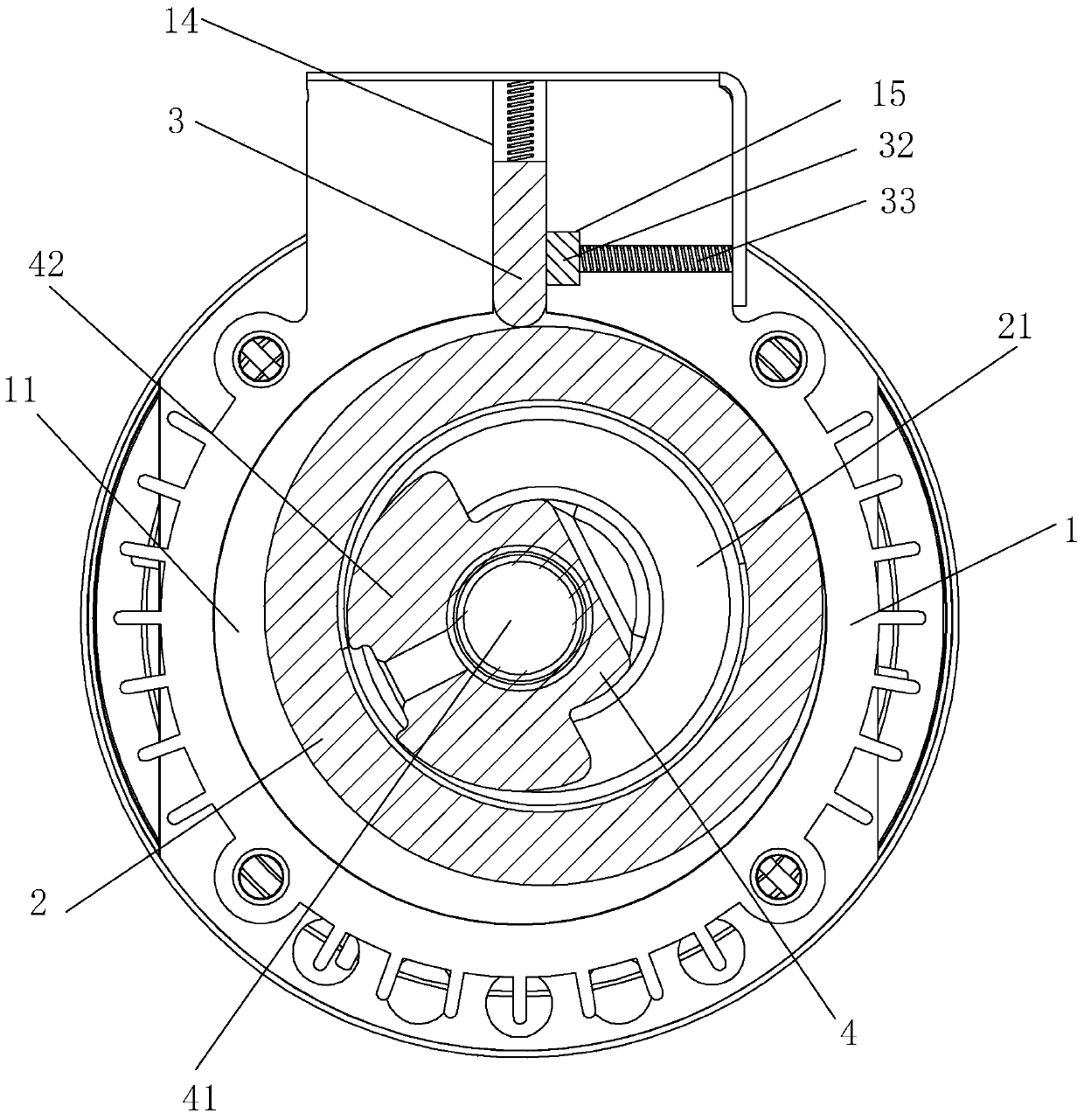
[0013] refer to Figure 1 to Figure 2 The embodiment of the head of the rotary air compressor of the present invention will be further described.

[0014] A head of a rotary air compressor, comprising a cylinder body 1, a translation piston 2, a slide plate 3, and a crankshaft. The rotation center of the crankshaft is concentric with the cylinder body 1, and the translation piston 2 is arranged on the crankshaft. The outer peripheral side of the movable piston 2 is tangent to the inner side of the circular cylinder 1 to form a crescent-shaped working chamber 11. The cylinder 1 is respectively provided with an air inlet passage 12 and an air outlet passage 13 communicating with the working chamber 11. The translational piston 2 is rotationally connected with the crankshaft through the bearing 21. The inner circumference side of the cylinder body 1 is provided with a mounting groove 14 for the installation of the slide plate 3. The slide plate 3 is installed in the mounting groo...


PUM


Abstract

The invention discloses a rotary air compressor head which comprises a cylinder body, a translation piston, a slide plate and a crankshaft, wherein a rotation center of the crankshaft is concentric with the cylinder body; the translation piston is arranged on the crankshaft; the side face of an external circumference of the translation piston is tangent with the inner side face of the circular cylinder body to form a crescent operation cavity; an air inlet channel and an air outlet channel communicated with the operation cavity are arranged on the cylinder body; the translation piston is rotationally connected with the crankshaft via a bearing; a mounting groove for mounting the slide plate is formed in the side face of an internal circumference of the cylinder body; the slide plate is mounted in the mounting groove; one end of the slide plate is contacted with the translation piston; an elastic return piece is arranged at one end, far away from the translation piston, of the slide plate; a slide groove is formed in a side wall of the mounting groove; a slide bar is arranged in the slide groove and pushes against the side face of the slide plate; and an elastic slide piece is arranged at one end, far away from the slide plate, of the slide bar. The air compressor head can keep stable compression efficiency and is long in service life, and the maintenance cost is lowered effectively.

Description

technical field [0001] The invention relates to the field of air compressor manufacturing, more specifically, it relates to a rotary air compressor head. Background technique [0002] The air compressor is an important general-purpose compression machine. The current rolling piston type compression machine (application number is 200410053347.9) will generate a large friction force between the piston and the sliding plate during operation, and the current flat The dynamic rotary compression device (application number 200820121680.2) avoids the large friction force at the end of the slide plate to prevent wear and improve the service life, but in these compression machines, the friction force generated between the slide plate side wall and the cylinder cannot be avoided. After a long time of use, the side wall of the slide plate wears more and the sealing effect between the slide plate and the cylinder body is greatly reduced, thereby reducing the efficiency of the air compres...

Claims


Application Information

Patent Timeline
Patent Type & Authority Patents(China)
IPC IPC(8): F04C18/356F04C29/00
Inventor 赵军正
Owner 台州阳光电机泵业有限公司
Why Eureka
Try Eureka