Rotary shaft, compressor and air conditioner

A compressor and rotating shaft technology, applied in the field of air conditioner equipment, can solve problems such as thrust surface wear, and achieve the effects of eliminating thrust sound, preventing axial movement, and improving stability and reliability.

Active Publication Date: 2017-02-22
GREE ELECTRIC APPLIANCES INC
View PDF5 Cites 4 Cited by
  • Summary
  • Abstract
  • Description
  • Claims
  • Application Information

AI Technical Summary

Problems solved by technology

[0003] The main purpose of the present invention is to provide a rotating shaft, a compr

Method used


Image

  • Rotary shaft, compressor and air conditioner
  • Rotary shaft, compressor and air conditioner
  • Rotary shaft, compressor and air conditioner

Examples


Embodiment Construction

[0032] It should be noted that, in the case of no conflict, the embodiments in the present application and the features in the embodiments can be combined with each other. The present invention will be described in detail below with reference to the accompanying drawings and examples.

[0033] It should be noted that the terminology used here is only for describing specific implementations, and is not intended to limit the exemplary implementations according to the present application. As used herein, unless the context clearly dictates otherwise, the singular is intended to include the plural, and it should also be understood that when the terms "comprising" and / or "comprising" are used in this specification, they mean There are features, steps, operations, means, components and / or combinations thereof.

[0034] It should be noted that the terms "first" and "second" in the description and claims of the present application and the above drawings are used to distinguish simila...


PUM


Abstract

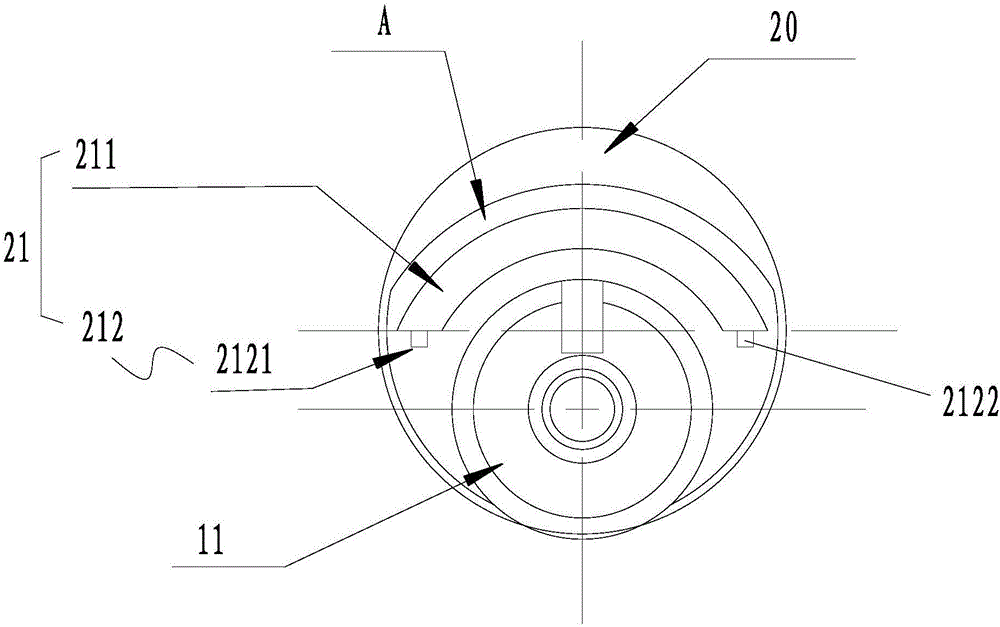
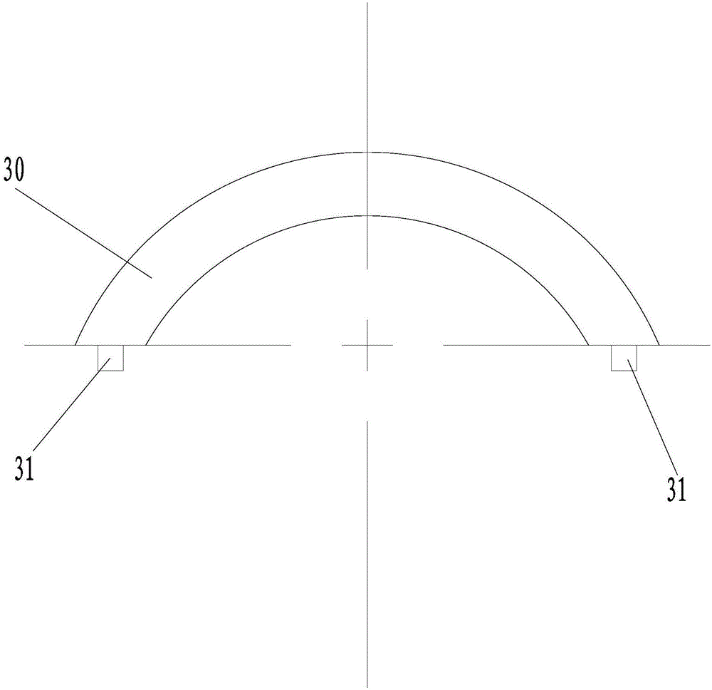
The invention provides a rotary shaft, a compressor and an air conditioner. The rotary shaft comprises a rotary shaft body, an eccentric part connected with the rotary shaft body and a buffering part arranged on a thrust surface of the eccentric part to reduce abrasion of the thrust surface. The buffering part arranged on the thrust surface of the eccentric part achieves a movable buffering effect in the axial direction, the rotary shaft can be effectively prevented from moving in the axial direction, thrust sound is eliminated, the problem that the thrust surface has friction with other components of an air cylinder, consequently the thrust surface has abrasion, and the reliability of the rotary shaft is lowered is effectively avoided, and therefore the stability and reliability of the rotary shaft are effectively improved.

Description

technical field [0001] The invention relates to the technical field of air conditioner equipment, in particular to a rotating shaft, a compressor and an air conditioner. Background technique [0002] In recent years, with the rapid development of rotary compressors, customers have higher requirements for reliability and stability while pursuing high energy efficiency of compressors. In the prior art, during the working process of the rotary compressor, the crankshaft is driven by the rotor to rotate at a high speed. The radial constraints are the inner hole of the upper flange and the inner hole of the lower flange, and the axial constraints are the lower end surface of the upper flange and the lower surface of the lower flange. The common design of the upper end face of the flange is: the eccentric portion of the crankshaft directly contacts the upper end face of the lower flange to support the crankshaft. The common design of the thrust surface of the crankshaft cannot ens...

Claims


Application Information

Patent Timeline
IPC IPC(8): F04C29/00F16C3/18F16C3/06
CPCF04C29/00F04C2240/60F04C2240/601F16C3/06F16C3/18
Inventor 陈辉叶晓飞王伟竺宁凯
Owner GREE ELECTRIC APPLIANCES INC
Why Eureka
Try Eureka