Impeller for an exhaust gas turbocharger

A technology for exhaust turbines and superchargers, applied in the direction of components of pumping devices for elastic fluids, machines/engines, blade support elements, etc., can solve the problem of limited, unsatisfactory loads, and reduce high tensile stress And other issues

Active Publication Date: 2017-02-22
BOSCH MAHLE TURBO SYST GMBH & CO KG
View PDF10 Cites 0 Cited by
  • Summary
  • Abstract
  • Description
  • Claims
  • Application Information

AI Technical Summary

Problems solved by technology

Under the influence of centrifugal forces on the suction side in the area of ​​attachment of the blades to the hub body, said backward bending leads to high tensile stresses that reduce the expected service life
However, higher rotational speeds and / or even more pronounced backward bending are only possible to a limited extent for service life reasons
Furthermore, the hub body commonly used today is constructed as a continuous circular body of rotation, this simple geometry is not ideal for the loads that occur especially at the transition between the blades and the hub body

Method used


Image

  • Impeller for an exhaust gas turbocharger
  • Impeller for an exhaust gas turbocharger
  • Impeller for an exhaust gas turbocharger

Examples


Embodiment Construction

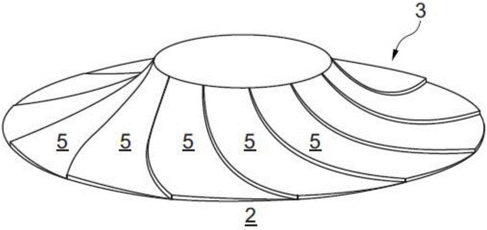
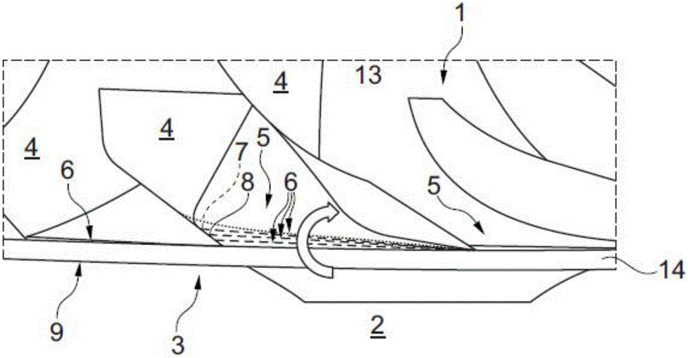
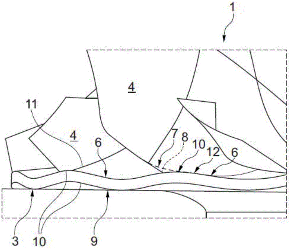
[0026] according to Figure 1 to Figure 5 , the impeller 1 according to the invention for an exhaust-gas turbocharger 2 has a hub body 3 and blades 4 arranged on said hub body 3 . figure 1 Only the hub body 3 is shown, not the associated blades 4 . In order to subsequently be able to optimize the impeller 1 according to the invention with regard to the stresses occurring in the region of the transition 7 between the individual blades 4 and the hub body 3, two alternative embodiments of the hub body 3 are provided, the first The replacement example is shown in figure 1 and figure 2 , while the second substitution example is shown in Figure 3 to Figure 5 middle.

[0027] according to figure 1 and figure 2 , the hub body 3 is here configured according to the invention as a polygon with a number of portions 5 inclined relative to each other, corresponding in number to the number of blades 4 . In this paper, each section 5 (see also figure 2 ) preferably has at least a ...


PUM


Abstract

An impeller (1) for an exhaust gas turbocharger (2) may include a hub main body (3) and blades (4) arranged thereon. The hub main body (3) may be configured as a polygon with a number of segments (5) that may be tilted with respect to one another, the number of the segments (5) corresponding to a number of the blades (4). Alternatively, the hub main body (3) may have a main surface (6) that faces the blades (4) and undulates in a circumferential direction, a number of the undulations (10) corresponding to the number of the blades (4).

Description

technical field [0001] According to the preamble of claim 1 , the invention relates to an impeller for an exhaust-gas turbocharger having a hub body and blades arranged on said hub body. Furthermore, the invention relates to an exhaust-gas turbocharger having an impeller of this type. Background technique [0002] US8721287B2 already discloses an impeller of the general type for an exhaust-gas turbocharger having a hub body and blades arranged on said hub body. In order to be able to reduce the loads, especially in the region of attachment of the blades to the hub body, the transition between the hub body and the blades is also rounded in an elliptical manner. [0003] As a rule, impellers consist of a hub body and blades arranged on said hub body, current impellers are usually equipped with a backward-curved impeller profile for thermodynamic reasons. Under the influence of centrifugal forces on the suction side in the region of attachment of the blades to the hub body, s...

Claims


Application Information

Patent Timeline
Patent Type & Authority Applications(China)
IPC IPC(8): F04D29/28F01D5/14
CPCF01D5/141F04D29/284F05D2250/73F05D2250/183F05D2220/40F05D2240/80F05D2250/184F05D2250/611F05D2250/18F01D5/04
Inventor 谢诺尔·瑟于特费利克斯·舍雷尔马丁·库恩
Owner BOSCH MAHLE TURBO SYST GMBH & CO KG
Why Eureka
Try Eureka