Weatherproof vanes with self-closing function

An automatic closing, fan blade technology, applied to fan blades. It can solve problems such as equipment and product loss, rainwater intrusion/inflow into the room, and interior space impact.

Active Publication Date: 2019-01-25
温岭市应达电器有限公司
View PDF4 Cites 0 Cited by
  • Summary
  • Abstract
  • Description
  • Claims
  • Application Information

AI Technical Summary

Problems solved by technology

[0002] The exhaust fan is a mechanism installed on the wall to ventilate the internal space and the external space. At present, the blades of the exhaust fan are all fixed and have a vortex-like dislocation structure layout of the fan blades. However, such a structure is currently When it rains, especially in the windy and rainy weather like a typhoon, the traditional wind blade structure is not sealed, and there is a large gap between the wind blades, so that rainwater will pour into / flow into the room from time to time, and then damage the interior. The impact on space, especially for some factories, whose equipment and products will suffer huge losses after being soaked by rainwater

Method used


Image

  • Weatherproof vanes with self-closing function
  • Weatherproof vanes with self-closing function
  • Weatherproof vanes with self-closing function

Examples


Embodiment 1

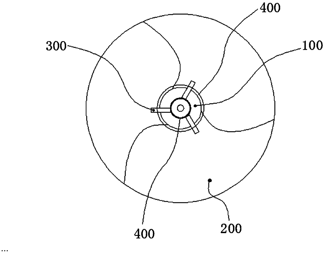
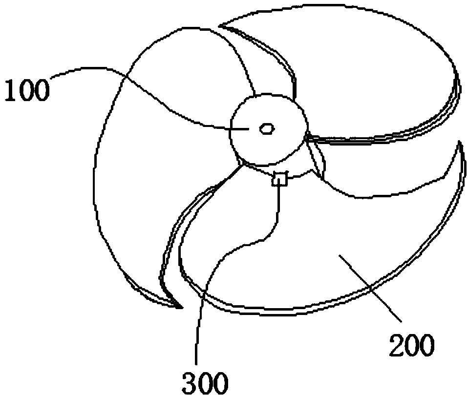
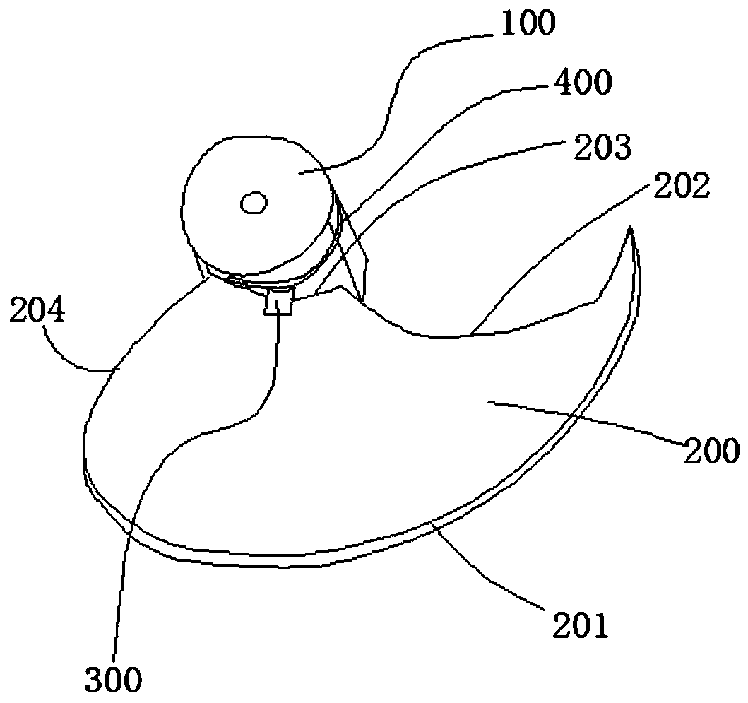
[0023] The dislocation mechanism is dislocated through the gravity difference on the blade and the gear 400, because the same blade needs to produce a weight difference, so the embodiment is illustrated by using the moon-shaped fan blade 200. The specific technical solution is as follows:

[0024] refer to Figure 1 to Figure 3 , the blade is divided into four sides: the connecting inner edge 203 facing the main shaft 100, the circular arc outer edge 201 opposite to the connecting inner edge 203 and forming an arc shape, and the second connecting inner edge 203 and the circular arc outer edge 201 respectively. An inner side 204 and a second inner side 202, the weight of the first inner side 204 is greater than that of the second inner side 202, and the motive force of dislocation is realized by the weight difference between the two sides. Of course, in order to ensure its sealing, the blades The first inner side 204 is adapted to the arc shape of the second inner side 202 of t...

Embodiment 2

[0029] The dislocation mechanism uses the cooperation of card displacement and guide rail 600, because the blade does not need to produce weight difference, so this embodiment is illustrated by fan-shaped fan blade, and its specific technical solution is as follows:

[0030] refer to Figure 4 to Figure 6 , the misalignment mechanism is a guide rail 600 arranged on the main shaft 100 and a linkage rod 900 arranged between each adjacent two blades 200 , and the reset mechanism is a return spring 800 arranged in the guide rail 600 . In the misalignment, the linkage rod 900 is used to ensure that the misalignment angles between multiple blades are unified and consistent.

[0031] Further design of the above technical solution: the guide rail 600 includes a first guide rail 602 that fixes the card when the blades are closed and a second guide rail 601 that fixes the card when the blades are unfolded, and a second limit position is set on the second guide rail 601 Buckle 700 , the...


PUM


Abstract

The invention discloses a weatherproof wind blade with an automatic closing function, and belongs to the field of wind dispelling or wind exhausting equipment. Staggering mechanisms are arranged on the blades; return mechanisms are arranged between main shafts and the blades; and when the blades are returned through the return mechanisms, and multiple blades are spliced as a complete closed circle, and are staggered through the staggering mechanisms, the blades are fixedly inclined on the main shafts to form a wind blade eddy current structure. The staggering mechanisms and the return mechanisms realize conversion of closing and unfolding states of the wind blades; when the wind blades work, the staggering mechanisms unfold the wind blades to form the wind blade eddy currents to realize the wind exhausting effect; and when the wind blades stop working, the return mechanisms return the wind blades to form a closed circle, and the adjacent blades are tightly bonded to realize a no-gap structure of an exhaust fan so as to achieve the weatherproof effect.

Description

technical field [0001] The invention belongs to the field of wind-dispelling or exhausting equipment, and in particular relates to a wind blade. Background technique [0002] The exhaust fan is a mechanism installed on the wall to ventilate the internal space and the external space. At present, the blades of the exhaust fan are all fixed and have a vortex-like dislocation structure layout of the fan blades. However, such a structure is currently When it rains, especially in the windy and rainy weather like a typhoon, the traditional wind blade structure is not sealed, and there is a large gap between the wind blades, so that rainwater will pour into / flow into the room from time to time, and then damage the interior. Space has an impact, especially for some factories, whose equipment and products will suffer huge losses after being soaked by rainwater. Especially for some granaries, for places with high requirements for ventilation and dryness, it is necessary to prevent rai...

Claims


Application Information

Patent Timeline
Patent Type & Authority Patents(China)
IPC IPC(8): F04D29/38
CPCF04D29/388
Inventor 叶恩平
Owner 温岭市应达电器有限公司
Why Eureka
Try Eureka