Brake disc processing technology and tooling

A processing technology and brake disc technology, which is applied in the direction of grinding workpiece supports, etc., can solve the problems of low processing efficiency and affect the production efficiency of brake discs, and achieve the effects of improving production efficiency, fitting precision, and improving grinding efficiency.

Active Publication Date: 2022-06-24
浙江隆中机械股份有限公司
View PDF6 Cites 0 Cited by
  • Summary
  • Abstract
  • Description
  • Claims
  • Application Information

AI Technical Summary

Problems solved by technology

[0005] In view of the above-mentioned related technologies, the inventor believes that when machining the center hole, the material is quickly removed by turning and a machining allowance is left, and then the finishing is completed by grinding. The machining efficiency is low during grinding, which affects the production efficiency of the brake disc.

Method used


Image

  • Brake disc processing technology and tooling
  • Brake disc processing technology and tooling
  • Brake disc processing technology and tooling

Examples


Embodiment Construction

[0052] Attached to the following Figure 1-8 This application will be described in further detail.

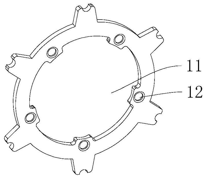
[0053] refer to figure 1 , the brake disc is annular, and the brake disc is provided with a central hole 11 and a mounting hole 12 .

[0054] The embodiment of the present application discloses a processing technology for a brake disc.

[0055] The machining process of brake disc includes blanking, inner hole, grinding inner hole, drilling mounting hole and grinding end face.

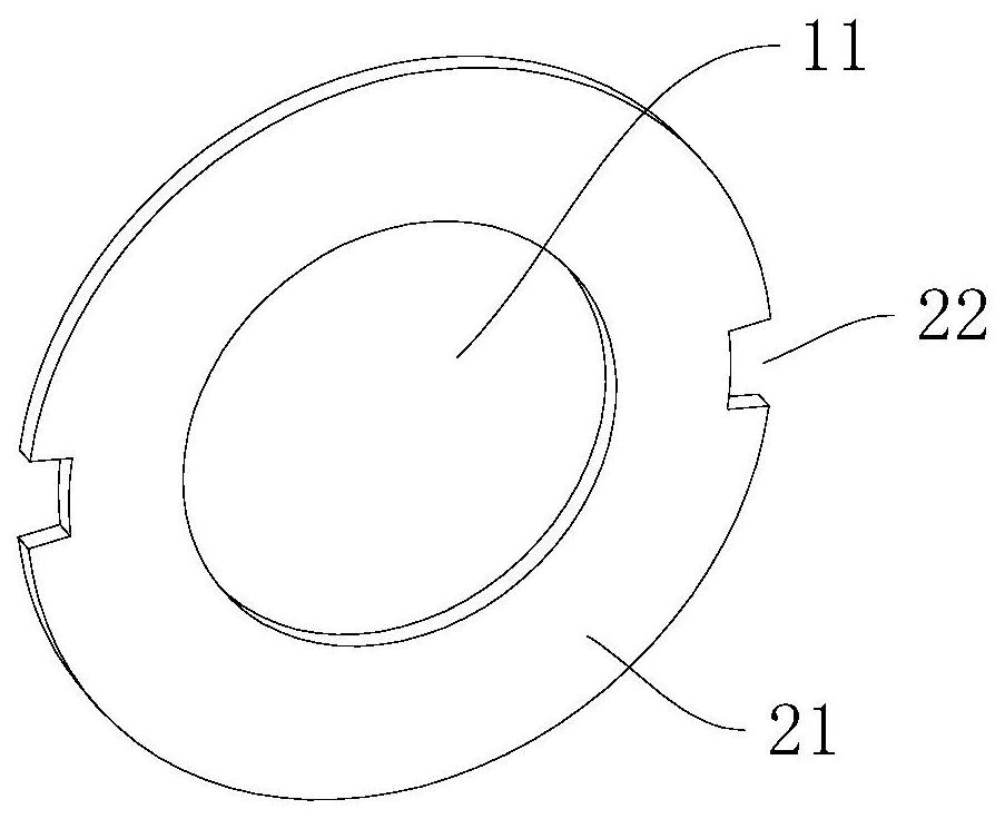
[0056] Step 1: Blanking. refer to figure 2, the sheet material is placed on the worktable, a circular substrate 21 is processed by laser cutting or punching, and two positioning grooves 22 are machined on the outer periphery of the substrate 21 that are symmetrical about the axis of the substrate 21, and the positioning grooves 22 are along the substrate 21. At the same time, the positioning groove 22 has three side walls, wherein the two opposite side walls of the positioning groove 22 along the c...


PUM


Abstract

This application relates to a brake disc processing technology and tooling. The processing technology includes blanking, car inner hole and grinding inner hole; step blanking: the sheet is placed on the workbench, and a circular shape is processed by cutting or punching. The base plate is processed with a positioning groove on the outer periphery of the base plate, and the positioning groove runs through the base plate along the thickness direction of the base plate; the inner hole of the step: clamp the outer periphery of the base plate, and turn the center hole on the base plate; the inner hole of the step grinding: multiple The base plates are coaxially stacked into a group, and the positioning grooves on each base plate are connected to each other. A set of base plates is installed on the tooling, and the grinding wheel rods are inserted into multiple center holes to grind the inner peripheries of the multiple center holes. Realize synchronous grinding of multiple basic center hole inner peripheries by using one grinding wheel rod, improve grinding efficiency, and further improve production efficiency of brake discs.

Description

technical field [0001] The present application relates to the field of brake disc processing, and in particular, to a brake disc processing technology and tooling. Background technique [0002] The brake is a component in the braking system used to generate a braking force that hinders the movement of the vehicle or the tendency to move. In addition to various retarding devices, automobile brakes are almost all friction brakes that use the friction between the fixed element and the working surface of the rotating element to generate braking torque. [0003] Among them, the rotating element in the friction pair of the disc brake is a disc-shaped brake disc, and its end face is the working surface. [0004] refer to figure 1 , the brake disc is annular, and the brake disc is provided with a central hole 11 and a mounting hole 12 . Generally, the machining process of brake disc includes blanking, machining center hole, machining mounting hole and machining shape structure. ...

Claims


Application Information

Patent Timeline
Patent Type & Authority Patents(China)
IPC IPC(8): B23P15/00B24B41/06
CPCB23P15/00B24B41/06
Inventor 张鹏
Owner 浙江隆中机械股份有限公司
Why Eureka
Try Eureka