Paper feeding mechanism for invoice printer

A technology for a printer and a paper feeding mechanism, which is applied to typewriters, printing devices, printing, etc., can solve the problems of reducing printing efficiency, printer paper jams, and inability to achieve continuous feeding of continuous invoice paper, and achieve the effect of improving printing efficiency.

Active Publication Date: 2021-06-22
NANJING HANMINGZHI INTELLIGENT TECHNOLOGY CO LTD
View PDF0 Cites 0 Cited by
  • Summary
  • Abstract
  • Description
  • Claims
  • Application Information

AI Technical Summary

Problems solved by technology

[0003] However, in the actual operation process, the printing and paper feeding of invoices is semi-automatic, which is to manually push the invoice paper to the designated position, and then the printer will send the printing paper into the printer through the rotation of the paper roller. The printing paper is sent out again, and the continuous feeding of the continuous invoice paper cannot be realized, thereby reducing the printing efficiency. The friction between the invoice paper and the paper roller is used to feed the invoice paper, which is often caused by the friction between the invoice paper and the paper roller. Insufficient friction causes the invoice paper to slide on the paper roller, and eventually the invoice paper cannot be conveyed into the paper roller. At the same time, when multiple sheets of printing paper are stacked together, it is often difficult to separate due to two adjacent sheets of paper or multiple sheets of invoice paper. Two or more sheets of invoice paper enter the main body of the printer at the same time, resulting in paper jams in the printer

Method used


Image

  • Paper feeding mechanism for invoice printer
  • Paper feeding mechanism for invoice printer
  • Paper feeding mechanism for invoice printer

Examples


Embodiment Construction

[0028] In order to make the technical means, creative features, goals and effects achieved by the present invention easy to understand, the present invention will be further described below in conjunction with specific embodiments.

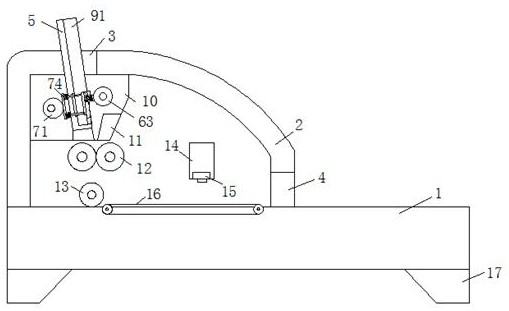
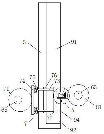
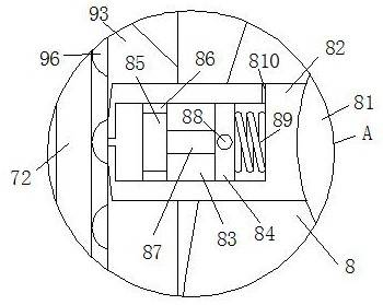
[0029] like Figure 1-Figure 9As shown, a paper feeding mechanism for an invoice printer according to the present invention includes a fixed base 1, a printer body 2, a paper inlet hole 3, a paper outlet hole 4, a deflector 5, a driving mechanism 6, an extrusion mechanism 7, The paper suction mechanism 8 and the storage mechanism 9, the upper end of the fixed base 1 is fixedly connected with a printer main body 2, the upper end of the printer main body 2 is provided with a paper inlet hole 3, and the lower end side of the printer main body 2 is provided with a paper output hole. Hole 4, inside the main body of the printer 2 and below the paper feed hole 3 is fixedly connected with a pair of fixed brackets 10, the deflector 5 is fixedly connected i...


PUM


Abstract

The invention relates to the field of printers, in particular to a paper feeding mechanism for an invoice printer, which includes a fixed base, a printer body, a paper inlet hole, a paper outlet hole, a deflector, a driving mechanism, an extrusion mechanism, a paper suction mechanism and a storage mechanism. mechanism, the upper end of the fixed base is fixedly connected with a printer main body, and a paper feeding hole is opened at the upper end of the printer main body. Through the rotation of the active shaft of the driving mechanism, the paper suction roller of the paper suction mechanism can be driven to rotate, and the piston plate can slide in the air cavity through the extrusion of the arc-shaped top plate to the pull rod, and finally the air suction head can suck the invoice The paper slides out from the front baffle of the storage mechanism, and is disconnected from the arc-shaped top plate through the pull rod, so that the air pressure suction head is disconnected from the invoice paper, and enters the main body of the printer for printing, realizing automatic paper feeding by the printer. It avoids the troublesome operation of manually sending invoices one by one to the designated position of the printer, and improves printing efficiency.

Description

technical field [0001] The invention relates to the field of printers, in particular to a paper feeding mechanism for an invoice printer. Background technique [0002] Invoice printers are different from common office laser printers. They are widely used in many occasions, such as printing invoices in shopping malls and supermarkets, and printers for printing value-added tax invoices used by companies for finance. In addition, there are many other Uses, such as portable ticket printers for traffic police to issue tickets on the spot, and invoice printers for finance. The printer mainly clamps and feeds the invoice paper through the paper feeding roller, and then transports the invoice paper to the bottom of the laser printing head through the guide roller On the conveying device, and through the sliding of the laser printing head, the laser printing is carried out on the printing paper, and finally the printing paper can flow out from the paper outlet hole. [0003] However...

Claims


Application Information

Patent Timeline
Patent Type & Authority Patents(China)
IPC IPC(8): B65H3/08B65H5/22B65H7/00B41J3/407B41J11/00
CPCB41J3/4075B41J11/006B65H3/08B65H5/22B65H7/00
Inventor 吴亚洲
Owner NANJING HANMINGZHI INTELLIGENT TECHNOLOGY CO LTD
Why Eureka
Try Eureka