
Gripper device of high frequency die cutting machine

A die-cutting machine and gripper technology, applied in the field of die-cutting machinery, can solve the problems of only 0.075 mm, poor paper quality, complex mechanism, etc., and achieve the effects of reducing waste, improving production efficiency, and high positioning accuracy

Active Publication Date: 2016-05-04
SHENZHEN REBORN PRECISION MACHINERY CO LTD
View PDF6 Cites 0 Cited by
  • Summary
  • Abstract
  • Description
  • Claims
  • Application Information

AI Technical Summary

Problems solved by technology

[0003] The high-frequency die-cutting machine needs to transport the paper to the die-cutting station for processing when it is working, but the existing high-frequency die-cutting machine mainly transports the paper to the die-cutting station for processing when it is working. Since the accuracy and stability of paper conveying is an important factor affecting the working quality of the die-cutting machine, the cardboard must be accurately conveyed to the station at a speed of 60-80 sheets per minute during work.
In order to achieve this goal, most of the paper feeding mechanisms on the market are driven by intermittent motion boxes, and are composed of conveyor chains, tooth rows and other components. The highest positioning accuracy is only 0.075 mm, and there are disadvantages such as complex mechanism, loud noise, high cost, low yield rate and poor paper quality

Method used


Image

  • Gripper device of high frequency die cutting machine
  • Gripper device of high frequency die cutting machine
  • Gripper device of high frequency die cutting machine

Examples


Embodiment Construction

[0038] In order to express the present invention more clearly, the present invention will be further described below in conjunction with the accompanying drawings.

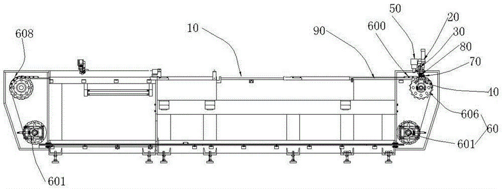
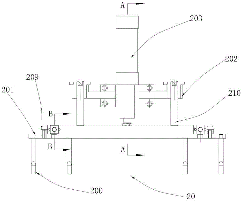
[0039] see figure 1 , the gripper device of the high-frequency die-cutting machine provided by the present invention includes a frame 10, a front gauge mechanism 20, a tooth row lifting mechanism 30, a front gauge position tooth row positioning mechanism 40, an opening and closing tooth row mechanism 50 and a chain transmission mechanism 60; the transmission chain 600 of the chain transmission mechanism 60 is connected with a tooth-opening slide mechanism 70, and the tooth-opening slide mechanism 70 is equipped with a tooth row 80 for clamping paper; the tooth row lifting mechanism 30 descends to push the tooth row 80 into the front The positioning mechanism 50 of the tooth row, the opening and closing tooth row mechanism 60 opens the tooth row 80 and waits for the paper to enter the gripper 800 of the tooth row 8...


PUM


Abstract

The invention discloses a gripper device of a high-frequency die cutting machine. The gripper device comprises a machine frame, a front guide mechanism, a gripper bar lifting mechanism, a front guide position gripper bar positioning mechanism, a gripper bar opening-closing mechanism and a chain transmission mechanism. A gripper opening slide plate mechanism is connected to a transmission chain of the chain transmission mechanism, and a gripper bar for clamping paper is installed on the gripper opening slide plate mechanism. The gripper bar lifting mechanism descends to push the gripper bar into the front guide position gripper bar positioning mechanism, the gripper bar opening-closing mechanism opens the gripper bar to wait for the paper to be fed into a gripper of the gripper bar, and the paper is lifted through a front guide rod in the front guide mechanism after being positioned by the front guide mechanism. The paper is clamped on the gripper bar after gripper bar opening-closing mechanism ascends to close the gripper bar, and the gripper bar moves on the working plane of the machine frame through the chain transmission mechanism after clamping the paper. The gripper device achieves automatic paper feeding, improves paper feeding speed, is high in paper positioning accuracy and further ensures paper weight, accordingly production efficiency is improved, processing effect is improved, and waste is reduced.

Description

technical field [0001] The invention relates to the field of die-cutting machinery, in particular to a gripper device of a high-frequency die-cutting machine. Background technique [0002] High frequency die cutting machine is the main equipment in the printing and packaging industry. The high-frequency principle generates a high-frequency electromagnetic field by a tube self-excited oscillator. The paper to be processed is pressed between the upper and lower electrodes with a high-frequency electromagnetic field, and its internal molecules are excited and high-speed motion rubs against each other to generate heat and melt, and achieve the purpose of welding or indentation under the pressure of the mold; die-cutting machine The working principle is to use the template carved by steel knife, metal mold, steel wire or steel plate, apply a certain pressure through the embossing plate, and cut the printed matter or cardboard into a certain shape. The main parts of the die-cutt...

Claims


Application Information

Patent Timeline
Patent Type & Authority Patents(China)
IPC IPC(8): B26D7/02B26D7/06
Inventor 邹平
Owner SHENZHEN REBORN PRECISION MACHINERY CO LTD
Learn More