
Printer and its control method, control device and system

A control method and control device technology, applied in printing, stamping, etc., can solve the problems of increasing the use of printing machine equipment, low processing efficiency, and increasing human resources investment, so as to improve the level of automation, improve the efficiency of printing, and realize automatic printing. Effect

Active Publication Date: 2016-06-01
INDUSTRIAL AND COMMERCIAL BANK OF CHINA
View PDF9 Cites 0 Cited by
  • Summary
  • Abstract
  • Description
  • Claims
  • Application Information

AI Technical Summary

Problems solved by technology

[0006] 3. The printing machine does not support batch stamping, and can only stamp on a single sheet of paper. If you encounter the scene of batch printing or mixed paper printing, the entire processing efficiency will become very low
[0007] 4. The image acquisition of the printing machine cannot be carried out simultaneously with the reset of the manipulator
The paper stamped by the printing machine often needs to be imaged for follow-up file management or auditing, but often because of the obstruction of the manipulator, it is necessary to wait for the manipulator to return the physical seal to its original position before the camera can process the stamp on the paper. Taking pictures and archiving is inefficient
[0008] The above-mentioned defects lead to the use of printers that cannot be used in business scenarios with a large amount of printing, and even have to increase the use of printing equipment and human resources to alleviate the problem of large demand for printing
[0009] Therefore, although the existing printing machines have solved the safety problem of manual printing, there are still problems such as low processing efficiency and too much manual participation in the printing process, which cannot well meet the needs of actual use.

Method used


Image

  • Printer and its control method, control device and system
  • Printer and its control method, control device and system
  • Printer and its control method, control device and system

Examples


Embodiment Construction

[0068] In order to make the object, technical solution and advantages of the present invention clearer, the present invention will be further described in detail below in conjunction with the embodiments and accompanying drawings. Here, the exemplary embodiments and descriptions of the present invention are used to explain the present invention, but not to limit the present invention.

[0069] The specific embodiment of the present invention will be further described in detail below in conjunction with the accompanying drawings.

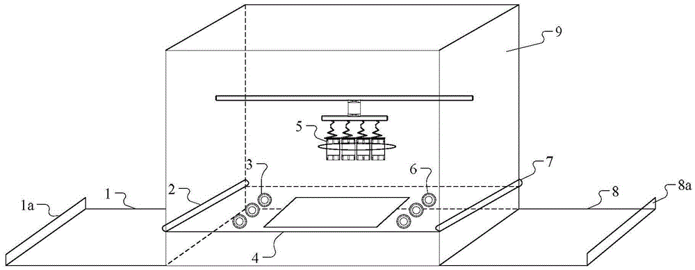
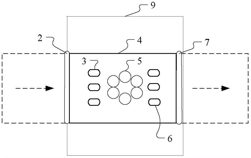
[0070] refer to figure 1 As shown, the printer according to the embodiment of the present invention includes a casing 9, which has the characteristics of a safe, such as high rigidity, fire prevention, and waterproof. This casing 9 is provided with safety door, and safety coded lock is housed on the safety door. The housing 9 is provided with a turntable stamp mechanism 5 configured with multiple stamps, and the printing machine also includes: a pa...


PUM


Abstract

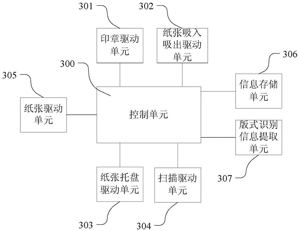
The invention provides a stamping machine and a control method and a control device thereof and a system. The stamping machine comprises a shell, an input tray, a paper suction-in mechanism, a paper feeding saddle, a paper driving device and a paper suction-out mechanism, wherein a stamp mechanism is arranged in the shell; the input tray is used for carrying paper to be stamped; the paper suction-in mechanism is used for sucking the paper on the input tray into the shell; the paper feeding saddle is provided with both a paper feeding passage and a stamp supporting table; the paper driving device is used for driving the paper to move left and right; the paper suction-out mechanism is used for sucking the stamped paper on the paper feeding saddle out of the shell. The stamping machine has high automation level and high stamping efficiency; by combining with the control method or the control device of the stamping machine, continuous work of automatic paper feeding, scanning, stamp selection and paper output of a batch of papers is realized.

Description

technical field [0001] The invention relates to automatic printing equipment, in particular to a printing machine and its control method, control device and system. Background technique [0002] With the emergence of the printing machine, it is realized that the physical seal is sealed in the printing machine, and the physical printing is completed by using the manipulator parts in the printing machine, thereby replacing the original manual printing process. Since the printing machine has a better security processing mechanism, it can solve the safety risk of manual printing. [0003] However, in the prior art, the exterior of the printer equipment is usually composed of a high-rigidity casing, and the interior includes components such as a stamp box, a robot arm, a camera, and a paper inlet and outlet. Due to the separate packaging with printing equipment, there are also the following defects during use: [0004] 1. The use of the printing machine requires manual particip...

Claims


Application Information

Patent Timeline
Patent Type & Authority Patents(China)
IPC IPC(8): B41K3/50B41K3/02
Inventor 郭锡超黄思颖鄞少芳张庆春
Owner INDUSTRIAL AND COMMERCIAL BANK OF CHINA
Learn More