Flow control method for heating heated fluid in stages by adopting heat exchange system

A technology of heating and heating fluid in stages, applied in the steam generation method, control system, steam generation method using solar energy, etc., can solve the problems of entropy increase, low energy utilization rate, etc. The effect of reducing the temperature difference between the inlet and outlet

Active Publication Date: 2017-02-22
HUAZHONG UNIV OF SCI & TECH
View PDF4 Cites 2 Cited by
  • Summary
  • Abstract
  • Description
  • Claims
  • Application Information

AI Technical Summary

Benefits of technology

This technology helps prevent differences from happening at both ends of two different types of equipment that are used for transferring thermal power or coolant (liquid). By reducing this distance, it improves efficiency while also increasing its ability to absorb more heat during operation.

Problems solved by technology

The technical problem addressed in this patented technology relates to improving the efficiency of an overall system that uses heat for producing high pressure gases through condensation refrigerators (CRCs). Previous designs had issues with maintaining consistently accurate temperatures due to changes caused by factors such as variations or fluctuations in coolant supply conditions.

Method used


Image

  • Flow control method for heating heated fluid in stages by adopting heat exchange system
  • Flow control method for heating heated fluid in stages by adopting heat exchange system

Examples


Embodiment Construction

[0014] In order to make the object, technical solution and advantages of the present invention clearer, the present invention will be further described in detail below in conjunction with the accompanying drawings and embodiments. It should be understood that the specific embodiments described here are only used to explain the present invention, not to limit the present invention. In addition, the technical features involved in the various embodiments of the present invention described below can be combined with each other as long as they do not constitute a conflict with each other.

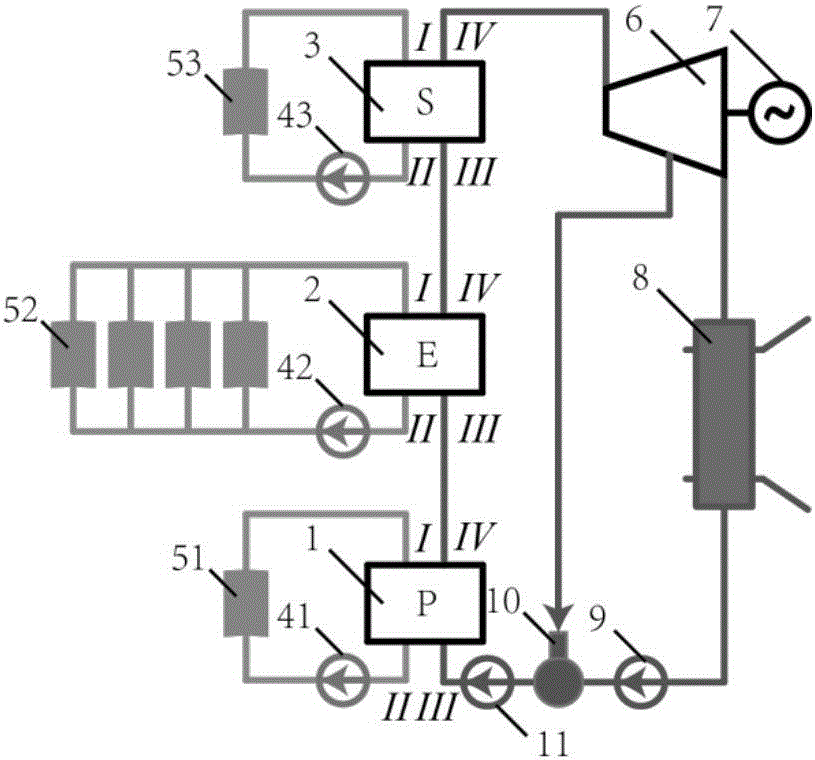
[0015] refer to figure 1 , a flow control method that uses a heat exchange system to heat the heated fluid in stages. The heat exchange system uses a heating fluid (preferably heat transfer oil) to heat the heated fluid (preferably water) from supercooled water to superheated gas, which includes Preheater 1, evaporator 2, superheater 3, steam turbine 6, generator 7, condenser 8, condensate pump...


PUM


Abstract

The invention belongs to the field of heat exchange equipment, and discloses a flow control method for heating a heated fluid in stages by adopting a heat exchange system. The heat exchange system comprises a pre-heater, an evaporator and a super-heater; the pre-heater is connected with the evaporator and the super-heater in sequence; the pre-heater is used for heating a sub-cooled fluid to a saturated fluid; the evaporator is used for heating the saturated fluid to a saturated gas; the super-heater is used for heating the saturated gas to a superheated gas. According to the flow control method for heating the heated fluid in stages by adopting the heat exchange system, the terminal temperature difference between an outlet and an inlet of each evaporator is reduced by controlling the flow of the heating fluid in the heat exchange system, so that the entropy production produced in a heat exchange process can be reduced; the energy utilization rate of the system is improved.

Description


Claims


Application Information

Patent Timeline
Owner HUAZHONG UNIV OF SCI & TECH
Why Eureka
Try Eureka