Method of Obtaining Cooling Water with Low Cooling Radius by Using Cooling Tower

A cooling tower and cooling water technology, applied in the field of cooling tower cooling system, can solve problems affecting the normal operation of refrigeration units, damage to refrigeration units, etc., and achieve the effects of easy implementation, improved efficiency, and simple methods

Inactive Publication Date: 2015-08-26
HENAN POLYTECHNIC UNIV
View PDF3 Cites 0 Cited by
  • Summary
  • Abstract
  • Description
  • Claims
  • Application Information

AI Technical Summary

Problems solved by technology

However, increasing the circulation flow will have adverse effects on both the cooling tower and the refrigeration unit. For example, the circulation flow of the cooling tower should be between 80% and 120% of its rated flow, otherwise it will affect its cooling effect and its structure. At the same time, if the circulating cooling water flow rate of the refrigeration unit is far from the design flow rate, it will affect the normal operation of the refrigeration unit and cause damage to the refrigeration unit

Method used


Image

  • Method of Obtaining Cooling Water with Low Cooling Radius by Using Cooling Tower
  • Method of Obtaining Cooling Water with Low Cooling Radius by Using Cooling Tower
  • Method of Obtaining Cooling Water with Low Cooling Radius by Using Cooling Tower

Examples


Embodiment Construction

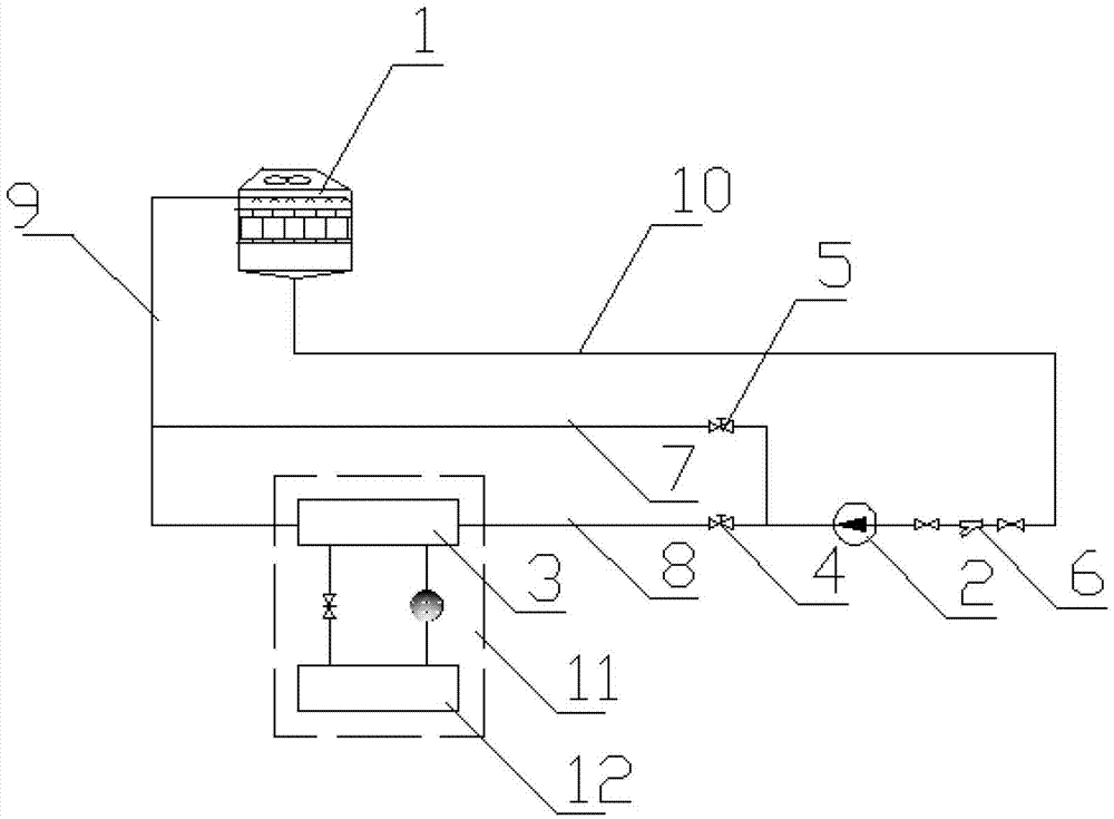
[0030] Such as figure 1 As shown, the cooling system of the present invention includes an existing cooling tower 1, a cooling water circulation pump 2, a refrigeration unit 11 made up of a condenser 3 and an evaporator 12, a first flow regulating valve 4, a pipeline filter 6, and cooling water return water The main pipe 9 and the water supply main pipe 10 can be seen from the figure, a bypass branch 7 is connected in parallel on the refrigerating unit branch 8, and a second flow regulating valve 5 is arranged on the bypass branch 7. During work, from the cooling The cooling water flowing out of the tower 1 passes through the cooling water supply main pipe 10 and is pressurized by the cooling water circulating pump 2 and then divided into two paths, one path passes through the refrigeration unit branch 8 and flows through the refrigeration unit condenser 3 to absorb heat and heat up, and the other path passes through the bypass branch 7 The temperature is basically unchanged. ...


PUM


Abstract

The invention discloses a method of obtaining low-approach cooling water by utilizing a cooling tower. A bypass branch passage with a flow regulating valve is connected with a circulating cooling water passage of a condenser of a refrigerating unit in parallel, water from the cooling tower is pressurized by a cooling circulating pump and then is divided into two paths, the water in one path flows through the branch passage of the condenser of the refrigerating unit, and the water in the other path flows through the bypass branch passage. The cooling water from the condenser of the refrigerating unit and the cooling water from of the bypass branch passage are mixed and then enter the cooling tower for circulating cooling. A flow G1 flowing through the branch passage of the refrigerating unit is required to be determined according to a designed cooling load of a refrigerating system, a flow G2 of the bypass branch passage is determined through calculation according to an approach required by circulating cooling water, and the flow of the cooling tower is determined according to the flow G1 of the branch passage of the refrigerating unit and the flow G2 of the bypass branch passage. Through technological improvement, the method obtains the low-approach cooling water by utilizing the cooling tower, and safe operation of the refrigerating system is not affected.

Description

technical field [0001] The invention relates to a cooling tower cooling system in a refrigeration system, in particular to a cooling tower cooling system using a cooling tower to obtain cooling water with a low cooling width. Background technique [0002] Cooling tower cooling system is an important part of the central air-conditioning centralized refrigeration system, which consists of cooling towers, cooling water circulation pumps, refrigeration units, pipelines and corresponding control and adjustment components. The cooling water cooling range of the cooling tower cooling system (the value of the outlet water temperature that the cooling tower can reach is higher than the local outdoor wet bulb temperature) is an important factor affecting the efficiency of the refrigeration system. According to statistics, within a certain temperature range, the efficiency of the refrigeration system will increase by about 4.5% for every 1°C decrease in the cooling range of the cooling...

Claims


Application Information

Patent Timeline
Patent Type & Authority Patents(China)
IPC IPC(8): F24F11/00
Inventor 徐文忠刘靖魏海霞冯永华
Owner HENAN POLYTECHNIC UNIV
Why Eureka
Try Eureka