Driving motor cooling system with defrosting function and application method

A technology for driving a motor and a cooling system, which is applied in the arrangement of the cooling combination of the power unit, the cleaning of the power unit, and the vehicle, etc., can solve problems such as increasing energy consumption, avoid excessive inlet water temperature, and prevent the defroster from entering. The effect of low water temperature

Inactive Publication Date: 2018-03-09
HUNAN CSR TIMES ELECTRIC VEHICLE
View PDF4 Cites 0 Cited by
  • Summary
  • Abstract
  • Description
  • Claims
  • Application Information

AI Technical Summary

Problems solved by technology

[0003] The invention provides a driving motor cooling system with a defrosting function and an application method to solve the technical problems in the prior art that additional defrosting equipment needs to be installed and additional energy consumption is required for defrosting

Method used


Image

  • Driving motor cooling system with defrosting function and application method
  • Driving motor cooling system with defrosting function and application method

Examples


Embodiment Construction

[0029] The present invention will be further described below in conjunction with accompanying drawing.

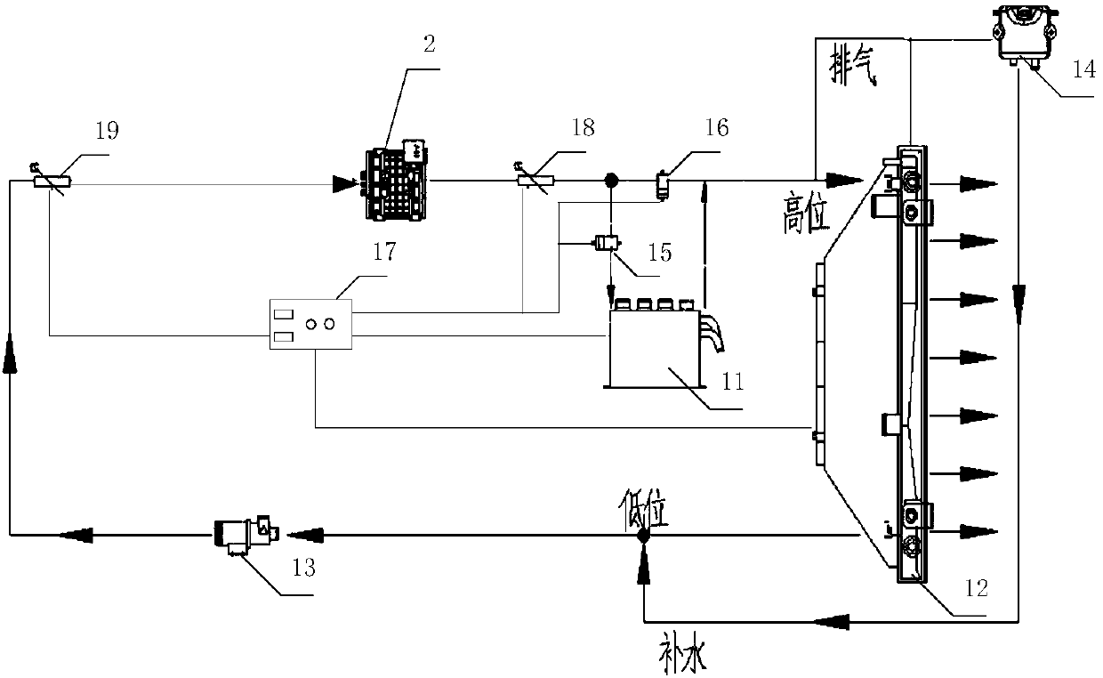
[0030] figure 1 A schematic structural diagram of a drive motor cooling system with a defrosting function provided in Embodiment 1 of the present invention; figure 1 As shown, the present embodiment provides a driving motor 2 cooling system with a defrosting function, including: a defroster 11, a radiator 12, a water pump 13 and a water tank 14, wherein the defroster 11 and the cooling liquid of the driving motor 2 The water inlet of outlet, radiator 12 is connected, and the water outlet of radiator 12 is connected with the water inlet of water pump 13, and the water outlet of water pump 13 is connected with the coolant inlet of drive motor 2, and the water inlet of water pump 13 is also connected with water tank 14.

[0031] Specifically, the defroster 11 can be a water-heating defroster 11 or a water-electric integrated defroster 11. The water pump 13 transports the cool...


PUM


Abstract

The invention provides a driving motor cooling system with a defrosting function and an application method. The system comprises a defroster, a radiator, a water pump and a water tank, wherein the defroster is connected with a cooling liquid outlet of a driving motor and a water inlet of the radiator, a water outlet of the radiator is connected with a water inlet of the water pump, a water outletof the water pump is connected with a cooling liquid inlet of the driving motor, and a water inlet of the water pump is further connected with the water tank. Heat of the driving motor is effectivelyutilized in the defroster, so that the problems about heat dissipation of the driving motor and the energy consumption of the defroster are solved, no extra energy consumption is needed for defrosting, resources are fully utilized, and the cost is reduced.

Description

technical field [0001] The invention relates to the technical field of electric passenger cars, in particular to a driving motor cooling system with a defrosting function and an application method. Background technique [0002] Since the new energy pure electric bus has no engine water cooling system, the structure of the windshield defrosting system of the whole vehicle is different from that of the traditional vehicle. At present, there are generally two types of windshield defrosting systems used in pure electric buses in the industry. The frost device is configured to convert the power consumed by the energy storage system of the pure electric vehicle into defrosting heat energy. This solution has a great impact on the cruising range of the vehicle under the current situation that the capacity of the energy storage battery is limited. The second is to use an independent water heating system with a fuel heater. This solution requires additional configurations such as a fu...

Claims


Application Information

Patent Timeline
IPC IPC(8): B60K1/00B60K11/02B60S1/54
CPCB60K1/00B60K11/02B60K2001/006B60S1/54
Inventor 杨浩李全陈玉德周宇周宏涛刘军伟陈亮曾青马强
Owner HUNAN CSR TIMES ELECTRIC VEHICLE
Why Eureka
Try Eureka