Efficient transcritical carbon dioxide refrigerating system

A carbon dioxide and refrigeration system technology, which is applied in the direction of refrigerators, refrigeration components, refrigeration and liquefaction, etc., can solve the problems of increasing the manufacturing cost of CO2 systems, and achieve the effects of increasing energy efficiency ratio, reducing use, and high energy efficiency

Active Publication Date: 2022-02-18
南京久鼎环境科技股份有限公司
View PDF6 Cites 0 Cited by
  • Summary
  • Abstract
  • Description
  • Claims
  • Application Information

AI Technical Summary

Problems solved by technology

[0004]Because the critical temperature of CO2 is only 30.98℃, but the critical pressure is as high as 7.38MPa, which is 3-4 times of the design pressure of Freon refrigeration system, which improves the CO2 system manufacturing cost

Method used


Image

  • Efficient transcritical carbon dioxide refrigerating system
  • Efficient transcritical carbon dioxide refrigerating system
  • Efficient transcritical carbon dioxide refrigerating system

Examples


Embodiment 1

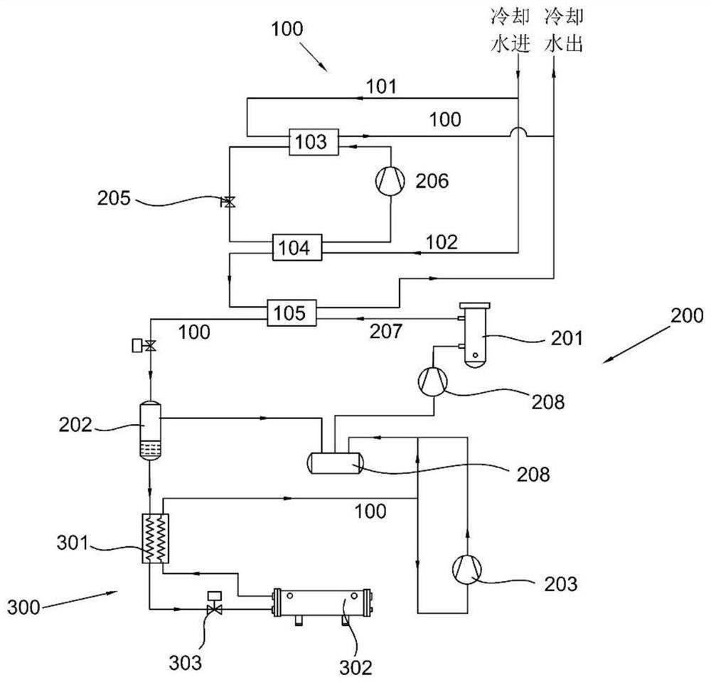
[0031] refer to figure 1 , the present invention discloses a high-efficiency transcritical carbon dioxide refrigeration system, including a water inlet assembly 100, including a first water inlet pipe 101, a second water inlet pipe 102 extending from the first water inlet pipe 101, and a The second condenser 103 on the water pipe 101 and the second evaporator 104 arranged on the second water inlet pipe 102, the end of the second water inlet pipe 102 away from the second evaporator 104 is provided with a gas cooler 105, the first water inlet pipe 101 and The far end of the second water inlet pipe 102 is connected to the water outlet pipe; the compression assembly 200 includes an oil fraction 201, a flash tank 202 connected to the oil fraction 201, and a first low-pressure stage compressor 203 connected to the water outlet of the flash tank 202; and, back to The heat component 300 and the heat recovery component 300 are arranged between the flash tank 202 and the first low-press...

Embodiment 2

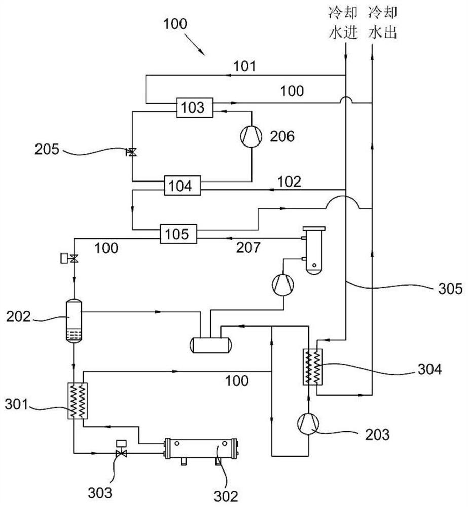
[0040] refer to figure 2 , this embodiment is different from the first embodiment in that: the first low-pressure stage compressor 203 is connected with a precooler 304, the second water inlet pipe 102 extends from the third water inlet pipe 305, and the third water inlet pipe 305 passes through The precooler 304 is connected to the outlet pipe afterward, and the first evaporator 302 is a sleeve-and-tube heat exchanger.

[0041] Specifically, on the basis of Implementation 1, the first low-pressure stage exhaust precooler 304 is added to reduce the exhaust temperature of the first low-pressure stage compressor 203 to 30-35°C through cooling water, further reducing the temperature of the first high-pressure stage compressor. The suction superheat degree of 209 also reduces the discharge temperature of the first high-pressure stage compressor 209, so that the discharge temperature of the compressor is controlled within the optimal range; in addition, the suction density of the ...

Embodiment 3

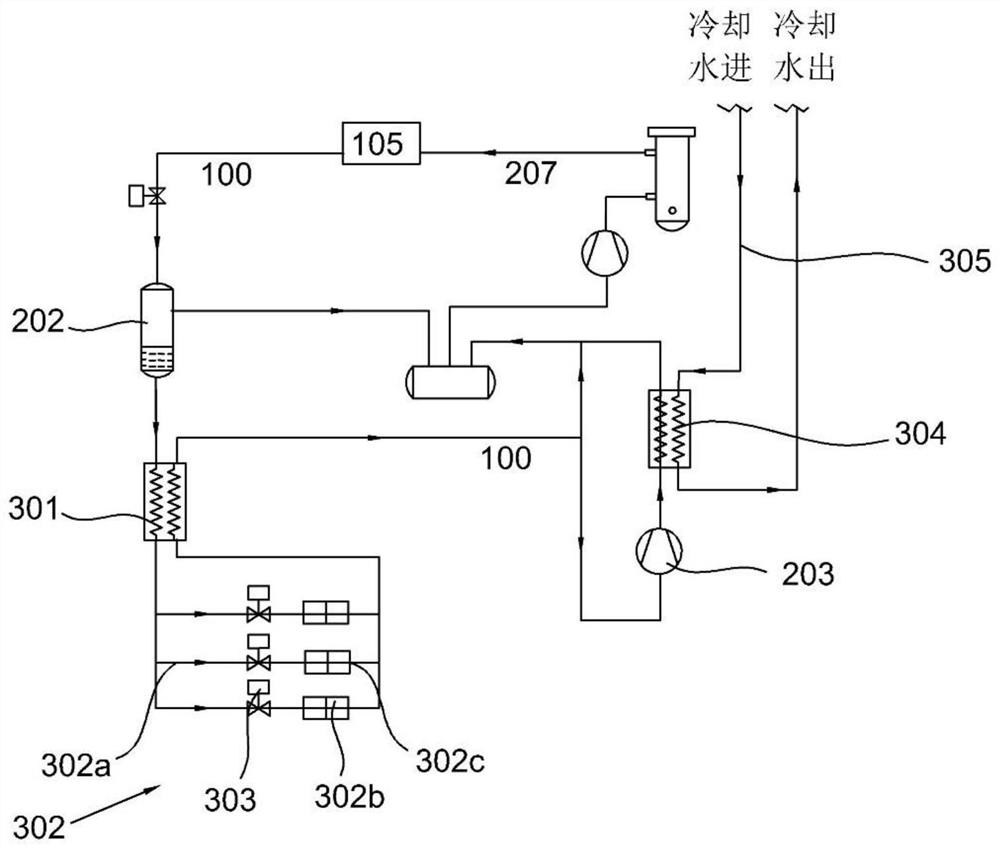
[0044] refer to image 3 , this embodiment is different from the above embodiments in that: the first evaporator 302 includes several branch pipes 302a protruding from the regenerator 301, a cooling fan 302b arranged on each branch pipe 302a, and a cooling fan 302b arranged on the cooling air The discharge pipe 302c on the machine 302b is connected to the regenerator 301 after the ends of several branch pipes 302a are connected.

[0045] All the other structures are the same as in Example 1.


PUM


Abstract

The invention discloses an efficient transcritical carbon dioxide refrigerating system which comprises a water inlet assembly. The water inlet assembly comprises a first water inlet pipe, a second water inlet pipe, a second condenser and a second evaporator. The second water inlet pipe extends out of the first water inlet pipe. The second condenser is arranged on the first water inlet pipe. The second evaporator is arranged on the second water inlet pipe. a gas cooler is arranged at one end, far away from the second evaporator, of the second water inlet pipe; the far ends of the first water inlet pipe and the second water inlet pipe are connected to a water outlet pipe; the system also comprises a compression assembly comprises an oil component, a flash tank connected with the oil component and a first low-pressure-stage compressor connected with the water outlet end of the flash tank; a heat regeneration assembly arranged between the flash tank and the first low-pressure-stage compressor. The water inlet temperature of cooling water is reduced through the second evaporator, the water temperature of an outlet of a cooling tower is reduced to 15-20 DEG C from 25-35 DEG C, the water temperature entering a gas cooler is reduced, the temperature of CO2 at an outlet of the gas cooler is reduced to 20-25 DEG C, and the temperature of CO2 at an outlet of the gas cooler is reduced to 20-25 DEG C; and the refrigerating capacity per unit mass of the first evaporator is increased.

Description

technical field [0001] The invention relates to the technical field of carbon dioxide refrigeration technology, in particular to an efficient transcritical carbon dioxide refrigeration system. Background technique [0002] With the development of refrigeration technology, new synthetic refrigerants continue to appear, and their global warming potential index (GWP) is relatively low, but due to the high price, the market acceptance is relatively low. In recent years, CO2, a natural environmentally friendly refrigerant, has received more attention again. Compared with other refrigerants, CO2 has a GWP value of 1. [0003] The physical properties of CO2 are stable, non-toxic, with good safety and stability, and no toxic gas will be produced as the temperature rises. CO2 is one of the important components of air. It comes from a wide range of sources. It is generally obtained from combustion waste gas, and its production cost is very low. [0004] Because the critical temperat...

Claims


Application Information

Patent Timeline
Patent Type & Authority Applications(China)
IPC IPC(8): F25B9/00F25B31/00F25B41/20F25B41/40F25B49/02
CPCF25B9/006F25B9/008F25B31/004F25B41/20F25B41/40F25B49/02
Inventor 周荣辉赵东华张显鹏
Owner 南京久鼎环境科技股份有限公司
Why Eureka
Try Eureka