
Double-channel temperature control device with supercooling enthalpy increasing function, control method and electronic equipment

A technology of a temperature control device and a control method, which is applied to subcoolers, mechanical equipment, lighting and heating equipment, etc., can solve the problems of large compressor specifications, high refrigeration system cost and energy consumption, and high compressor input power, and achieves The effect of increasing the cooling capacity, improving the cooling capacity and improving the degree of subcooling

Active Publication Date: 2021-11-30
BEIJING JINGYI AUTOMATION EQUIP CO LTD
View PDF5 Cites 6 Cited by
  • Summary
  • Abstract
  • Description
  • Claims
  • Application Information

AI Technical Summary

Problems solved by technology

[0005] With the development of the current memory chip technology, the demand for the cooling capacity of the low-temperature channel of the temperature control device is gradually increasing. At present, the etching process of advanced memory chips requires The low temperature range required for the low temperature channel of the temperature control device is about -20 ~ -40 ° C, the temperature control range of the high temperature channel is 10 ~ 90 ° C, and the low temperature channel is under the working condition of -40 ~ -20 ° C. For the currently more commonly used R404a , R410a and other medium-temperature refrigerants have a low COP under low-temperature conditions, and increasing the cooling capacity requires a high input power of the compressor, resulting in generally large specifications of low-temperature channel compressors, and high cost and energy consumption of the refrigeration system

Method used


Image

  • Double-channel temperature control device with supercooling enthalpy increasing function, control method and electronic equipment
  • Double-channel temperature control device with supercooling enthalpy increasing function, control method and electronic equipment
  • Double-channel temperature control device with supercooling enthalpy increasing function, control method and electronic equipment

Examples


Embodiment Construction

[0076] Example embodiments will now be described more fully with reference to the accompanying drawings. Example embodiments may, however, be embodied in many forms and should not be construed as limited to the embodiments set forth herein; rather, these embodiments are provided so that this application will be thorough and complete, and will fully convey the concept of example embodiments to those skilled in the art. The same reference numerals denote the same or similar parts in the drawings, and thus their repeated descriptions will be omitted.

[0077] Furthermore, the described features, structures, or characteristics may be combined in any suitable manner in one or more embodiments. In the following description, numerous specific details are provided in order to give a thorough understanding of the embodiments of the application. However, those skilled in the art will appreciate that the technical solutions of the present application may be practiced without one or mor...


PUM


Abstract

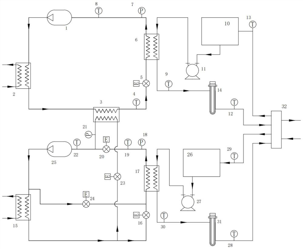
The invention provides a dual-channel temperature control device, a control method and electronic equipment. The dual-channel temperature control device comprises a low-temperature channel refrigerating system, a high-temperature channel refrigerating system and a supercooling heat exchanger; the high-temperature channel refrigerating system comprises a high-temperature channel compressor, a high-temperature channel evaporator, a high-temperature channel water tank, a high-temperature channel condenser, a high-temperature channel evaporator, a high-temperature channel main path expansion valve, a high-temperature channel main path pressure sensor and a high-temperature channel evaporator outlet temperature sensor; and the low-temperature channel refrigerating system comprises a low-temperature channel suction pressure sensor, a low-temperature channel suction temperature sensor and a low-temperature channel expansion valve. A path of evaporator is separated from the high-temperature channel refrigerating system, supercooling enthalpy increasing is carried out on liquid of the low-temperature channel refrigerating system, and the unit refrigerating capacity of the low-temperature channel refrigerating system is improved.

Description

technical field [0001] The application relates to the field of semiconductor manufacturing, in particular to a dual-channel temperature control device with supercooling and enthalpy increase, a control method and electronic equipment. Background technique [0002] In the semiconductor memory chip manufacturing process, during the etching process, the etching equipment uses a special temperature control device to control the temperature in the processing chamber in real time by continuously feeding a constant temperature circulating fluid into the internal flow channel of the processing device. [0003] With the development of the 3D NAND process, in the etching process of the memory chip, each etching process needs to be performed at different temperatures. The temperature switching time in the processing chamber affects the processing cycle of the chip, and fast temperature switching can effectively improve the chip processing efficiency. [0004] In order to reduce the te...

Claims


Application Information

Patent Timeline
Patent Type & Authority Applications(China)
IPC IPC(8): F25B1/00F25B40/02F25B41/31F25B49/02F25B41/20H01L21/311
CPCF25B1/00F25B40/02F25B41/31F25B49/02F25B41/20H01L21/311
Inventor 刘紫阳靳李富胡文达常鑫芮守祯曹小康董春辉
Owner BEIJING JINGYI AUTOMATION EQUIP CO LTD
Learn More