
Loading mechanism for testing rigidity of hydrostatic guide rail

A technology of loading mechanism and static pressure guide rail, which is applied in the field of precision and ultra-precision machining, can solve the problems of inability to generate tension, discontinuous loading force, low efficiency, etc., and achieve the effect of large-scale adjustment

Active Publication Date: 2017-02-22
INST OF MACHINERY MFG TECH CHINA ACAD OF ENG PHYSICS
View PDF7 Cites 6 Cited by
  • Summary
  • Abstract
  • Description
  • Claims
  • Application Information

AI Technical Summary

Problems solved by technology

[0003] In order to overcome the shortcomings of low efficiency, discontinuous loading force, inability to generate tension and easy generation of displacement errors in the static pressure guide rail stiffness test device in the prior art, the present invention provides a static pressure guide rail stiffness test loading mechanism

Method used


Image

  • Loading mechanism for testing rigidity of hydrostatic guide rail
  • Loading mechanism for testing rigidity of hydrostatic guide rail
  • Loading mechanism for testing rigidity of hydrostatic guide rail

Examples


Embodiment 1

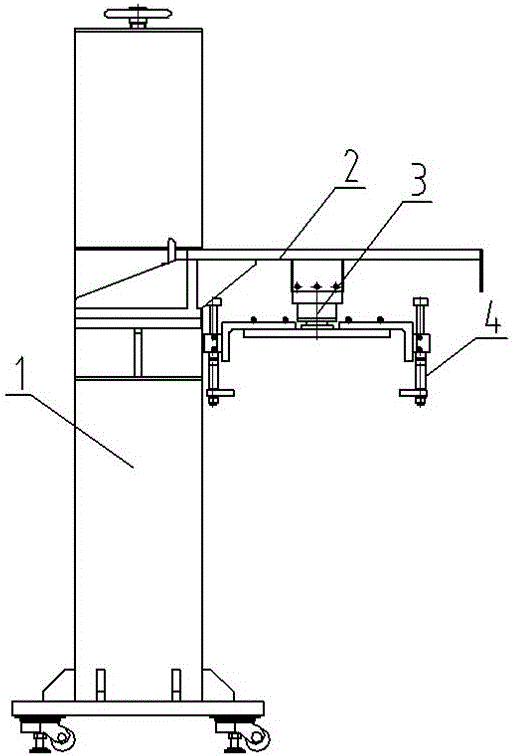
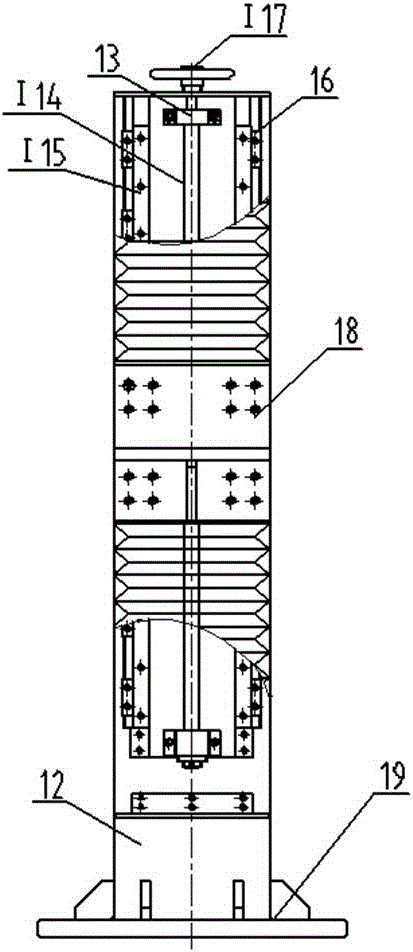
[0025] figure 1 It is a structural schematic diagram of a static pressure guide rail stiffness test loading mechanism of the present invention, figure 2 It is a structural schematic diagram of the vertical guide rail unit in the present invention, image 3 It is a structural schematic diagram of the horizontal guide rail unit in the present invention, Figure 4 It is a structural schematic diagram of the indexing unit and the loading force applying unit in the present invention. exist Figure 1~Figure 4 Among them, the loading mechanism of the hydrostatic guide rail stiffness test of the present invention includes a vertical guide rail unit 1, a horizontal guide rail unit 2, an indexing unit 3, and a loading force applying unit 4. Wherein, the vertical guide rail unit 1 includes a fixed side 11, a column 12, a support side 13, a ball screw I14, a non-interchangeable slide rail I15, a locking block 16, a hand wheel I17, a horizontal guide rail mounting plate 18, a base 19....

Embodiment 2

[0034] The structure of this embodiment is the same as that of Embodiment 1, the difference is that there are 20 locking blocks.


PUM


Abstract

The invention discloses a loading mechanism for testing the rigidity of a hydrostatic guide rail. In the loading mechanism, a stand column of a vertical guide rail unit is fixed on a base; a transverse guide rail mounting plate is mounted on a ball screw I in the stand column; a horizontal guide rail unit is mounted on the transverse guide rail mounting plate; a worktable in the horizontal guide rail unit is mounted on a ball screw II; a connecting bearing seat in an indexing unit is mounted on the worktable; and a fixed seat in a loading force applying unit is mounted on an upper adjusting plate in the indexing unit. The horizontal guide rail unit, the vertical guide rail unit and the indexing unit are arranged so that the adjustment of a space position of a loading force applying mechanism is realized and the loading force applying mechanism is adaptive to different guide rails; a differential nut in the loading force applying unit realizes slow feeding of a screw in the vertical direction, so that accurate application of a loading force is realized; and meanwhile, the loading force applying unit is internally connected with a sensor so that the loading force can be measured in real time. According to the loading mechanism disclosed by the invention, loss-free application of the loading force and the adjustment of positions, directions and sizes in a relative large range can be realized.

Description

technical field [0001] The invention belongs to the field of precision and ultra-precision machining, and specifically relates to a static pressure guide rail stiffness test loading mechanism, the structure can be adjusted to adapt to guide rails of different sizes, and the direction of loading force can be adjusted to meet the measurement requirements of the vertical stiffness and angular stiffness of the guide rail. The magnitude of the force can be adjusted continuously and precisely. Background technique [0002] At present, with the wide application of hydrostatic guide rails, the requirements for stiffness detection of hydrostatic guide rails are getting higher and higher. In previous stiffness tests, weights of different weights were added as variable loads. However, when weights are placed on the slide table of the guide rail, there will be a slight movement of the slide table, and the movement of the slide table will cause deviations in the measurement data of the ...

Claims


Application Information

Patent Timeline
Patent Type & Authority Applications(China)
IPC IPC(8): G01M5/00
CPCG01M5/0025
Inventor 丁颖刘有海夏欢王宝瑞张连新阳红崔海龙吴祉群吕磊
Owner INST OF MACHINERY MFG TECH CHINA ACAD OF ENG PHYSICS
Learn More