
A dual-rotor synchronous reversing device

A technology of reversing devices and dual rotors, which is applied in measuring devices, testing of machines/structural components, instruments, etc., can solve the problems of not using dual-rotor synchronous reversing devices, etc., so as to achieve reduced space occupation, low implementation cost, and reduced The effect of taking up space

Active Publication Date: 2018-10-26
LOW SPEED AERODYNAMIC INST OF CHINESE AERODYNAMIC RES & DEV CENT
View PDF6 Cites 0 Cited by
  • Summary
  • Abstract
  • Description
  • Claims
  • Application Information

AI Technical Summary

Problems solved by technology

However, due to the late start of domestic research on high-speed helicopters, there is no relevant test device at present, and there is no dual-rotor synchronous inversion device applied to wind tunnel tests.

Method used


Image

  • A dual-rotor synchronous reversing device
  • A dual-rotor synchronous reversing device
  • A dual-rotor synchronous reversing device

Examples


Embodiment Construction

[0022] In order to make the object, technical solution and advantages of the present invention clearer, the present invention will be described in detail below in conjunction with the accompanying drawings and specific embodiments. It should be understood that the specific embodiments described here are only used to explain the present invention, not to limit the present invention.

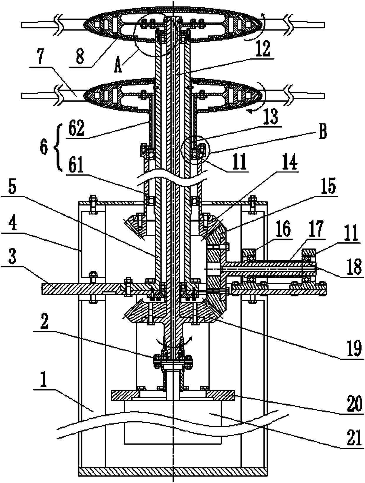
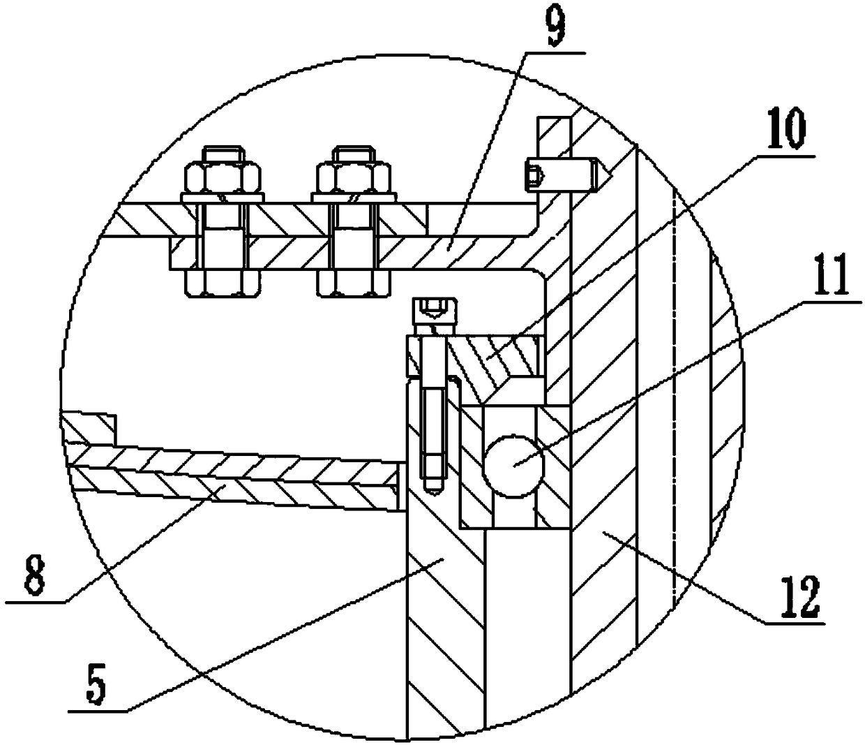
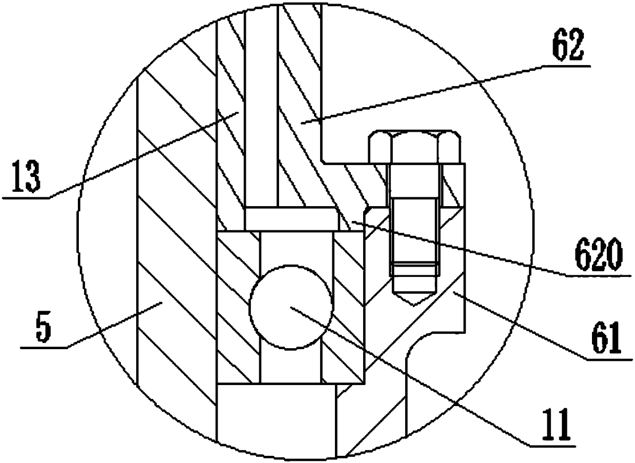
[0023] Such as figure 1 The shown double-rotor synchronous reversing device mainly includes a support frame and a power output mechanism, a power decomposition mechanism and a transmission mechanism installed on the support frame. In order to facilitate processing and assembly, the support frame includes an upper support 4, a lower support 1 and a fixed support 3, and the upper support 4 and the lower support 1 are respectively located on the upper and lower opposite sides of the fixed support 3, and are connected by bolts. Fixed connection into one. The power output mechanism includes a motor 2...


PUM


Abstract

The invention provides a double-rotor-wing synchronous reversing device, and the device comprises a supporting frame, a power output mechanism, a power decomposition mechanism and a transmission mechanism, wherein the power output mechanism, the power decomposition mechanism and the transmission mechanism are disposed in the supporting frame. The transmission mechanism comprises an external cylinder (6) and an internal cylinder (12), wherein the internal cylinder (12) passes through the external cylinder (6), and the internal cylinder (12) and the external cylinder (6) are respectively in fixed connection with the power decomposition mechanism. The power output mechanism drives the internal cylinder (12) to rotate, and the power decomposition mechanism drives the external cylinder (6) and the internal cylinder (12) to rotate synchronously, wherein the rotating direction of the external cylinder (6) is opposite to the rotating direction of the internal cylinder (12). The device is simple and compact in structure, and is small in occupied space. When the device is used for a wind tunnel test, the internal cylinder (12) and the external cylinder (6) are respectively in fixed connection with an upper rotor wing and a lower rotor wing. In other words, the device can drive two rotor wings to rotate coaxially, synchronously and oppositely through one motor. The device is small in face area, can maintain lower wind tunnel blocking degree, is small in interference with a flow field, and can guarantee the reliability of a test result.

Description

technical field [0001] The invention relates to the technical field of twin-rotor coaxial helicopter tests, in particular to a double-rotor synchronous reversing device applied to wind tunnel tests. Background technique [0002] Existing helicopters with conventional configurations are not suitable for time-sensitive tasks due to their low flight speed and short range. The high-speed helicopter designed with various advanced technologies such as the concept of forward blades has broken through the forward flight speed limit of conventional configuration helicopters, and its maximum cruising speed reaches 463Km / h, which is 1.5 times that of conventional configuration helicopters. However, this high-speed helicopter has the problem of huge hub resistance during the test flight, and it needs to consume 45% of the power of the whole machine to overcome the hub resistance. This problem has therefore become a major obstacle in the process of developing a high-speed helicopter. ...

Claims


Application Information

Patent Timeline
Patent Type & Authority Patents(China)
IPC IPC(8): G01M9/04
CPCG01M9/04
Inventor 何龙王畅唐敏黄明其杨永东武杰张卫国
Owner LOW SPEED AERODYNAMIC INST OF CHINESE AERODYNAMIC RES & DEV CENT
Learn More