Eureka AIR delivers breakthrough ideas for toughest innovation challenges, trusted by R&D personnel around the world.

A high-speed wind tunnel UAV launch test mechanism

A high-speed wind tunnel and unmanned aerial vehicle technology, applied in the direction of aerodynamic test, machine/structural component test, instrument, etc., can solve the problems of high cost, complicated control mechanism, large blockage in the test section, etc., and achieve low cost , Simplified operation steps, less blocking effect

Active Publication Date: 2020-01-10
NANJING UNIV OF AERONAUTICS & ASTRONAUTICS
View PDF1 Cites 0 Cited by
  • Summary
  • Abstract
  • Description
  • Claims
  • Application Information

AI Technical Summary

Problems solved by technology

[0006] The prior art (CN104931222A) discloses a machine-bomb separation and capture test system, in which the separation body support drive mechanism includes a rolling control device and a linear motion control device, and its control mechanism is complicated, which greatly blocks the test section of the high-speed wind tunnel
The cost of the device is prohibitive for some specific launch trials

Method used


Image

  • A high-speed wind tunnel UAV launch test mechanism
  • A high-speed wind tunnel UAV launch test mechanism
  • A high-speed wind tunnel UAV launch test mechanism

Examples


Embodiment Construction

[0050] specific implementation plan

[0051] In order to make the object, technical solution and advantages of the present invention clearer, the present invention will be further described in detail below in conjunction with the embodiments and accompanying drawings. It should be understood that the specific embodiments described here are only used to explain the present invention, and are not intended to limit the present invention.

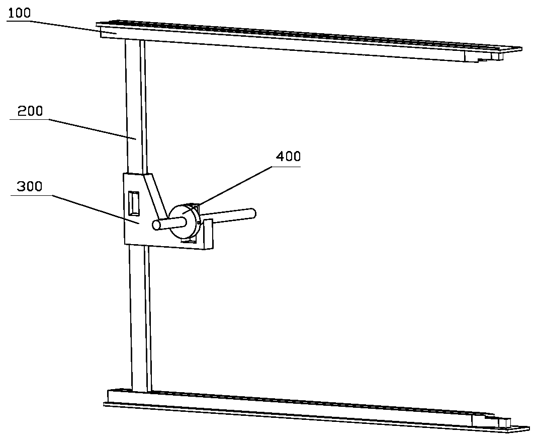
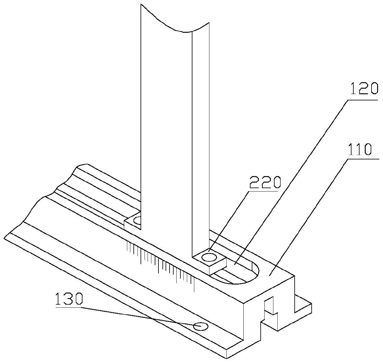
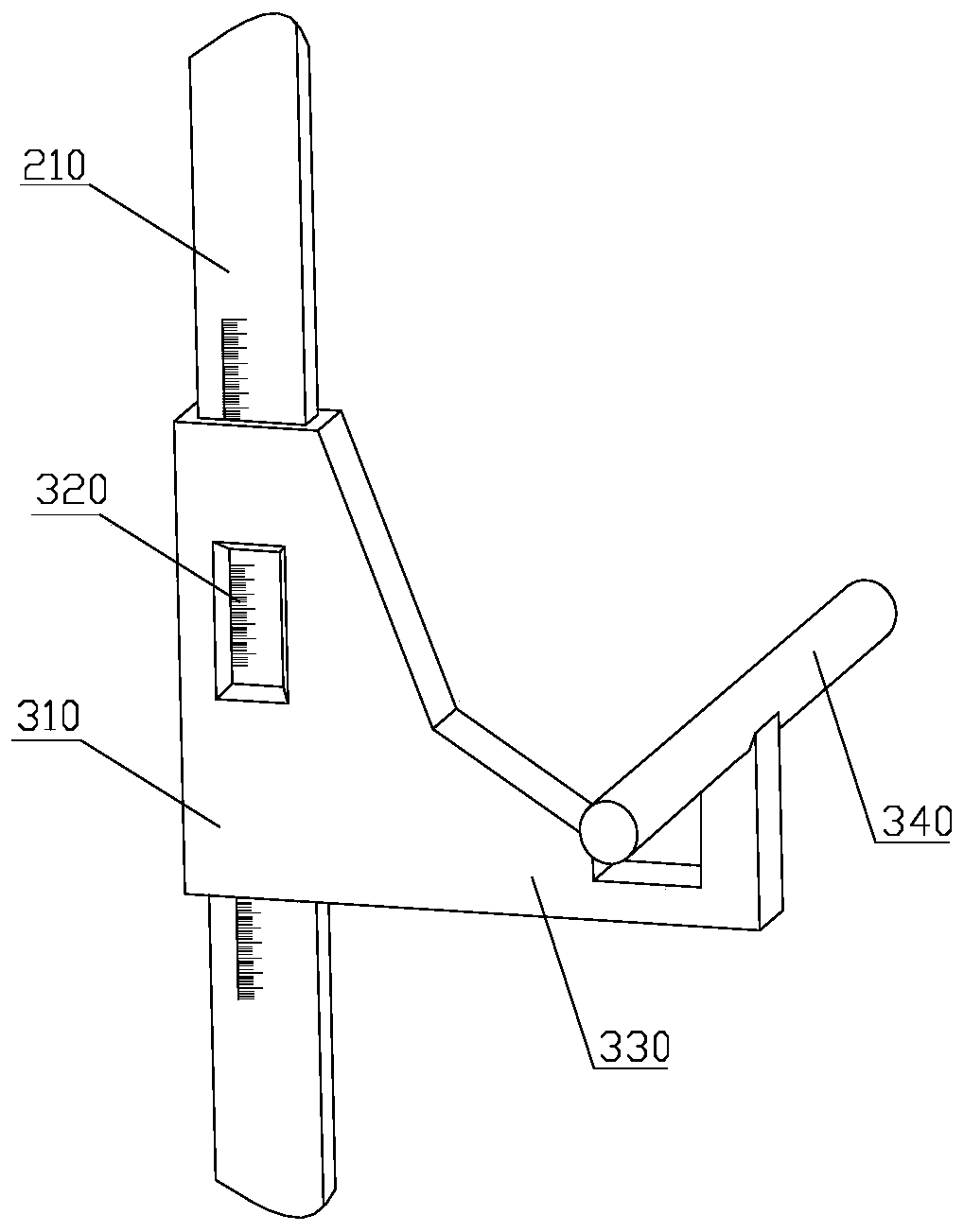
[0052] like figure 1 , a high-speed wind tunnel delivery device, including upper and lower guide rails 100, vertical beams 200, vernier slider 300, angle of attack ring 400.

[0053] like figure 1 , the upper and lower guide rails 100 are connected with the vertical beam 200, and the vertical beam 200 can move back and forth (X direction) relative to the upper and lower guide rails 100; direction); the angle of attack ring 400 is connected with the vernier slider 300 , and the angle of attack ring 400 can rotate on the vernier slider 300 i...


PUM


Abstract

The invention relates to a wind tunnel test device, and more particularly, relates to a high-speed wind tunnel unmanned aerial vehicle launching test mechanism. The mechanism is a three-degree of freedom mechanism (in short, a vertical beam and slider mechanism) formed by upper and lower guide rails, a vertical beam, a vernier slider and an attack angle ring, wherein the vertical beam can realizefront-back (X direction) movement along the upper and lower guide rails; the vernier slider can realize up-down (Y direction) sliding along the vertical beam; and the rotary attack angle ring is in charge of setting of the attack angle of a launched object. The device has the advantages of simple structure, accurate simulation, high precision, simple state change and low cost, and particularly, due to the light structure and corresponding small blocking interference, a critical important role is played in correct throwing object load extraction.

Description

technical field [0001] The invention relates to a wind tunnel test device, in particular to a high-speed unmanned aerial vehicle delivery test mechanism. [0002] technical background [0003] When the aircraft is flying, after the drop is launched or dropped from the aircraft, due to the mutual interference between the aircraft and the drop, it will have a great impact on the safe flight of the aircraft. The motion trajectory is simulated for measurement. [0004] There are currently two typical wind tunnel testing techniques that can be used to measure the trajectory of a droplet separating from an aircraft. That is, the free throw technology and the capture trajectory test technology. The advantage of the free drop technology is that it is not interfered by the support system of the external model, and the drop trajectory is close to the real trajectory, but the disadvantage of this technology is also very obvious, and it is very complicated to realize in a high-speed wi...

Claims


Application Information

Patent Timeline
Patent Type & Authority Patents(China)
IPC IPC(8): G01M9/04
CPCG01M9/04
Inventor 董昊刘是成程克明耿玺刘松夏天宇张亚晓
Owner NANJING UNIV OF AERONAUTICS & ASTRONAUTICS
Why Eureka
Eureka Blog
Learn More