Eureka AIR delivers breakthrough ideas for toughest innovation challenges, trusted by R&D personnel around the world.

A side-slip mechanism in a wind tunnel that can realize positive and negative conversion of the side-slip angle and has a small blocking ratio

A technology of sideslip angle and blocking ratio, which is applied in the field of a mechanism to realize the side slip angle of the transformation model, which can solve the problems of reducing the blocking ratio, large size of the turntable, and large blocking, so as to reduce the blocking degree and make the installation simple and reliable Effect

Active Publication Date: 2019-09-06
CHINA ACAD OF AEROSPACE AERODYNAMICS
View PDF5 Cites 0 Cited by
  • Summary
  • Abstract
  • Description
  • Claims
  • Application Information

AI Technical Summary

Problems solved by technology

[0003] The technical problem to be solved by the present invention is that the size of the turntable is larger when the conventional turntable sideslip mechanism achieves a large sideslip angle, so that the blockage is relatively large. The sliding mechanism solves this problem by designing a combination of two side-slip angle changes, which not only reduces the blocking ratio but also increases the range of the realized side-slip angle.

Method used


Image

  • A side-slip mechanism in a wind tunnel that can realize positive and negative conversion of the side-slip angle and has a small blocking ratio
  • A side-slip mechanism in a wind tunnel that can realize positive and negative conversion of the side-slip angle and has a small blocking ratio
  • A side-slip mechanism in a wind tunnel that can realize positive and negative conversion of the side-slip angle and has a small blocking ratio

Examples


Embodiment Construction

[0016] The present invention will be described in further detail below in conjunction with the accompanying drawings and specific embodiments.

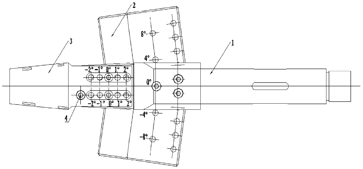
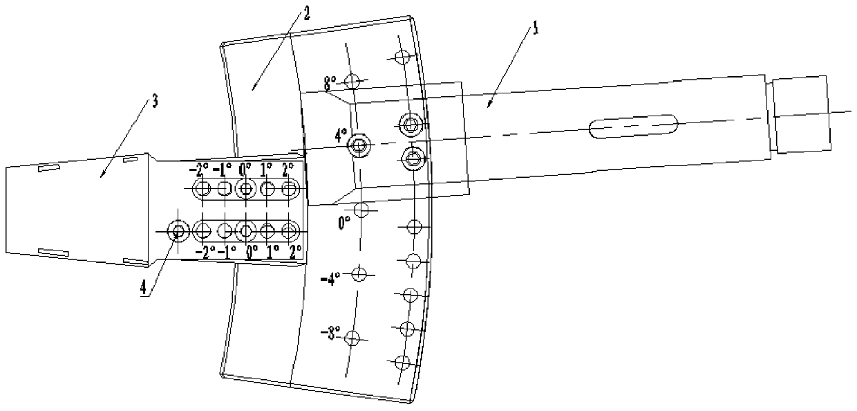
[0017] Such as Figure 1-3 As shown, the sideslip angle designed in this example ranges from -10° to 10°, and the minimum angle interval is 1°. The mechanism includes support 1, turntable 2 and joint 3, and support 1 and turntable 2 pass through three pin holes Connected, the turntable 2 is a fan structure with a mounting bump at the center, and the center part of the fan is inserted into the groove of the support 1.

[0018] Three pin holes are set on the groove of the support 1 for fixed connection with the pin holes on the fan surface, wherein one pin hole A1 on the groove of the support 1 is located on the axis of the support 1, and the other two pin holes are on the axis of the support 1. The pin holes B2 and C2 are located on the same arc segment H2; a pin hole A1 is set on the center line of the sector 0 ’, the interval angle...


PUM


Abstract

The invention relates to a wind tunnel sideslip mechanism capable of realizing positive and negative conversion of a sideslip angle and with a small blockage ratio. A support (1) and a turnplate (2) are connected through three column pin holes; the turnplate (2) adopts sector structures with mounting bumps in the centers; the sector central part is inserted into a groove of the support (1); and three column pin holes are formed in the groove of the support (1) and are used for being connected with the corresponding column pin holes in the sector. The wind tunnel sideslip mechanism adopts two sector structures instead of the traditional single-sector structure, and the sideslip angle is converted by combining the angles of the two sectors; the projection area of the whole sideslip mechanism on the cross section of the wind tunnel is reduced by reducing the size of the big sector structure, so the blockage degree of the sideslip mechanism is reduced and establishment of a wind tunnel flow field is benefited; the small sector structure is added, so that the size reduction of the big sector is guaranteed, the sideslip angle range which can be realized by the sideslip mechanism is not reduced, and the requirements of most of transverse experiments are met; and the wind tunnel sideslip mechanism can meet most of experiments of the wind tunnels with sideslip angles, and is simple and reliable in mounting through verification.

Description

technical field [0001] The invention belongs to the field of experimental aerodynamics, and relates to a mechanism for realizing the transformation model side slip angle in a high-speed wind tunnel. Background technique [0002] The lateral aerodynamic characteristic test of an aircraft is an important wind tunnel test. The sideslip angle mechanism is a mechanism that realizes the lateral transformation of the attitude angle of the model. Usually, the sideslip mechanism is in the form of a turntable, and there are different pin holes on the turntable. The seat cooperates with different pin holes to achieve different sideslip angles. When a large sideslip angle test is required, a side-slip mechanism with a larger turntable size is required, but it will lead to an increase in the blocking ratio of the side-slip mechanism. In addition, in some cases, the size of the model is larger, which will cause wind tunnel flow. It is difficult to establish the field, and the shock wave ...

Claims


Application Information

Patent Timeline
Patent Type & Authority Patents(China)
IPC IPC(8): G01M9/04
Inventor 闫卫锋钱丹丹吴军飞
Owner CHINA ACAD OF AEROSPACE AERODYNAMICS
Why Eureka
Eureka Blog
Learn More