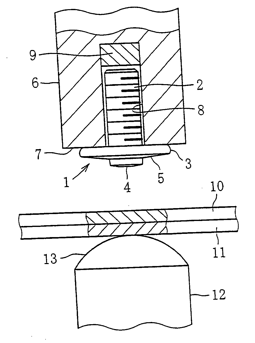
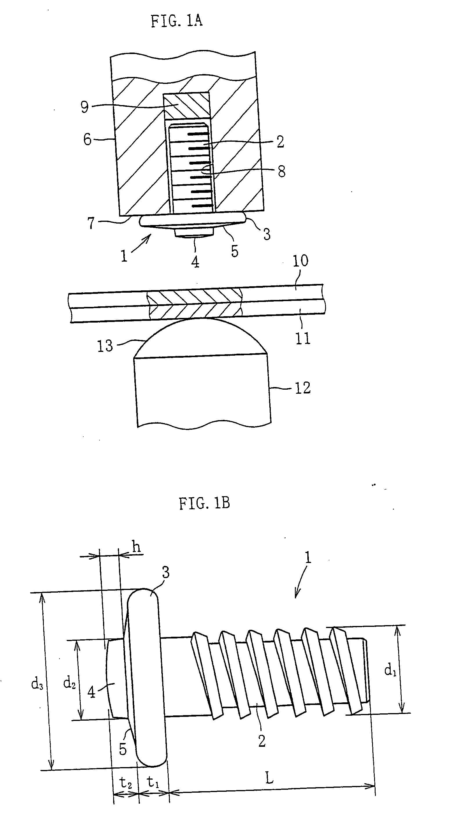
[0004] The present invention has been proposed to solve the problems described above. The invention resides in inserting a shaft-like part composed of a stem portion, a flange integrally formed on the stem portion, and a flat-headed projection disposed at the center of the flange and smaller in
diameter than the flange, at its stem portion into a holding hole in a movable electrode, stacking a plurality of steel sheets so as to keep the stack in contact with a fixed electrode, advancing the movable electrode to press the projection against the steel sheet so as to reduce the thickness of at least the steel sheet pressed by the projection, and passing a welding current through the two electrodes.
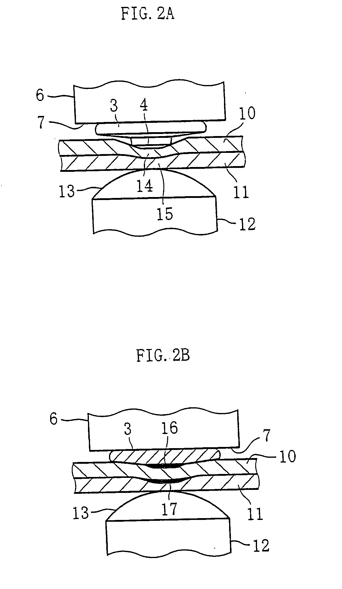
[0005] Since the flat-headed projection smaller in
diameter than the flange of the shaft-like part reduces the thickness of the independent single steel sheet pressed by the projection, as described above (
swaging), the volume of
metal at the start of melting has been reduced because of the reduction of the thickness and the reduction of the area of the projection, as describe above. At the same time as the start of passage of
electricity, this volume-reduced
metal portion rapidly evolves heat; thus, the melting of
metal is reliably started. With this melting of metal, the projection also melts, so that welding between the flange and the steel sheet in contact with the same reliably proceeds. Along with the proceeding of welding, the melting of the contact portion between the steel sheets also proceeds, and finally the welding between the flange and the steel sheet in contact therewith and the welding between the steel sheets are reliably effected. Therefore, the welding of the shaft-like part, and the integration of the steel sheets are simultaneously achieved in a sufficiently welded state at the time of the welding of the shaft-like part. Thus, this dispenses with the step of spot-welding steel sheets in advance, and is useful for improving productivity. Further, since the weld in the shaft-like part coincides with the weld in the steel sheets in the direction of the thickness of the steel sheet, the welding-integration between the shaft-like part and the steel sheets is achieved substantially at a single place, thus attaining simplification from the standpoint of welding construction and securing a sufficient
weld strength.
[0006] At the same time as the thickness of the steel sheet pressed by the projection is reduced, the thickness of the steel sheet in contact with the fixed electrode may also be reduced. When the thickness of the steel sheet in contact with the fixed electrode is thus reduced, the heat evolution or melting of this steel sheet is rapidly and reliably effected to form a predetermined nugget, as in the case of the steel sheet in contact with the projection.
[0007] The flange surface may preferably be pressed against the surface of the steel sheet in that the projection cuts into the steel sheet. Since the projection is welded to the thin steel sheets in a state in which the former cuts into the latter, it follows that the flange is pressed against the surface of the steel sheet. Therefore, the welding to the steel sheet is accomplished at the center of the flange, with the entire region Of the flange being pressed against the surface of the steel sheet, thus improving the joining rigidity of the shaft-like part. That is, even if an external force tending to tilt the shaft-like part acts on the stem portion, this does not lead to a phenomenon in which the stem portion easily tilts, since the entire region of the flange is pressed against the thin steel sheet.
[0008] The welding ranges between the projection and thin steel sheet and between the steel sheets are wider than the surface area of the projection. Since the projection cuts into the thin steel sheet and melts from its center toward the outer periphery, the melting is not limited to the range of the projection alone but extends to a range wider than the surface area of the projection, forming a sufficiently wide melt section, making it possible to secure a weld quality of high strength.
[0009] The number of steel sheets may be three. Since the initial melting is reliably attained by reducing the thickness of the thin steel sheet in contact with the projection by means of the projection, as described above, the melting of the respective intimately contacted portions of the steel sheets is effected simultaneously or subsequently. Therefore, even in the case of three steel sheets, the individual steel sheets are reliably welded, to say nothing of the welding of the shaft-like part, by increasing the pressing force on the movable electrode or increasing the welding current.

