
Multi-layer lattice precipitation separating device for V-shaped pipe

A technology of precipitation separation and vertical plate, applied in the direction of sedimentation tank, can solve the problems of reducing water flow area, reversible precipitation of suspended matter, unfavorable precipitation of suspended matter, etc., to achieve the effect of improving precipitation efficiency, simplifying construction and construction difficulty

Inactive Publication Date: 2012-07-11
厦门飞华环保有限公司
View PDF7 Cites 7 Cited by
  • Summary
  • Abstract
  • Description
  • Claims
  • Application Information

AI Technical Summary

Problems solved by technology

[0003] 1. When water flows through inclined pipes or inclined plates (in the same direction or in different directions), the direction of water flow needs to be changed, and the state of water flow changes, which is not conducive to the precipitation of suspended solids;
[0004] 2. In the process of water flowing through the inclined tube or inclined plate, it will have the effect of scouring and agitating the settled suspended solids, and the settled suspended solids will often be stirred up again by the water flow, resulting in reversible precipitation of the suspended solids;
[0005] 3. When the inclined tube (inclined plate) assembly is installed, two triangular dead zones will be formed, which reduces the utilization rate of the sedimentation tank and reduces the water flow area
[0008] 2. The mud passage has a certain inclination, and the sludge is easy to stay on the slope plate of the mud passage and cause blockage, which requires frequent flushing of the mud passage

Method used


Image

  • Multi-layer lattice precipitation separating device for V-shaped pipe
  • Multi-layer lattice precipitation separating device for V-shaped pipe
  • Multi-layer lattice precipitation separating device for V-shaped pipe

Examples


Embodiment Construction

[0025] The present invention will be further described in detail below in conjunction with the accompanying drawings and specific embodiments.

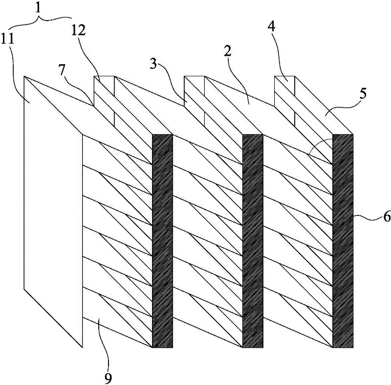
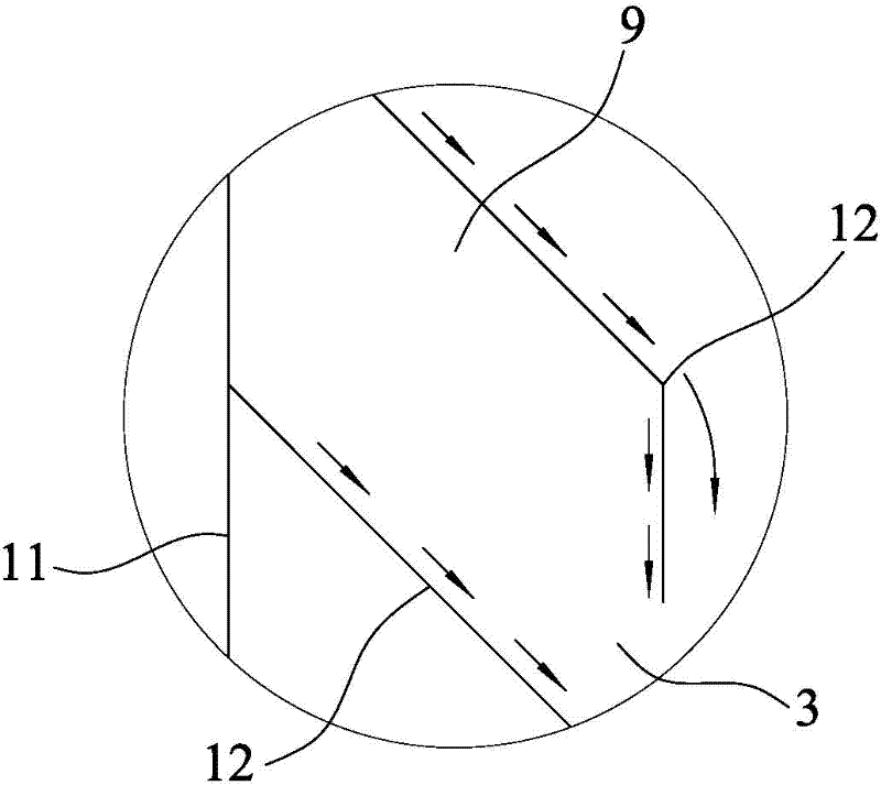
[0026] What the present invention discloses is a kind of V-shaped pipe multi-layer sedimentation separation device, such as Figure 2 to Figure 5 Shown is a preferred embodiment of the present invention. The V-shaped tube multi-layer sedimentation and separation device includes multiple groups of parallel vertical plates 1, each group of parallel vertical plates is composed of a left vertical plate 11 and a right vertical plate 12, and the angle between the left and right vertical plates 11, 12 and the horizontal plane 90 °, between the left and right vertical plates 11,12 is provided with a plurality of partitions 2, the partitions 2 are separated between the left and right vertical plates 11,12 several water flow channels 9 with a parallelogram in cross-section, the right vertical There is a mud discharge port 3 above the intersect...


PUM


Abstract

The invention discloses a multi-layer lattice precipitation separating device for a V-shaped pipe. The device is characterized by comprising multiple groups of parallel vertical plates, each group of parallel vertical plates is formed by a left vertical plate and a right vertical plate, a plurality of oblique clapboards are arranged between the left and right vertical plates, the left and right vertical plates and two adjacent clapboards form a water passage with a parallelogram-shaped cross section, a mud discharge hole is formed above the intersected part of the right vertical plate and the clapboard, a mud discharge passage is arranged between each right vertical plate and clapboards in another group of adjacent parallel vertical plates, and two ends of the mud discharge passage are sealed to form a static liquid area. As the vertical plates are adopted in the invention, the precipitation efficiency is improved, and simultaneously the vertical plates are more convenient to construct.

Description

technical field [0001] The invention relates to a water treatment device, in particular to a device for separating water and suspended matter in a sedimentation tank. Background technique [0002] With the development of urban water supply, various forms of sedimentation tanks developed from shallow pond theory have also been widely used. Including inclined plate sedimentation tanks, inclined tube sedimentation tanks, labyrinth sedimentation tanks, etc., but the above-mentioned sedimentation tanks (including the same direction, different direction, and horizontal sedimentation tanks) have the following disadvantages: [0003] 1. When water flows through inclined pipes or inclined plates (in the same direction or in different directions), the direction of water flow needs to be changed, and the state of water flow changes, which is not conducive to the precipitation of suspended solids; [0004] 2. In the process of water flowing through the inclined tube or inclined plate, ...

Claims


Application Information

Patent Timeline
IPC IPC(8): B01D21/02
Inventor 施世英
Owner 厦门飞华环保有限公司
Learn More