Projective lighting device and film component used therein

A lighting device and film technology, applied in projection devices, optical components, optics, etc., can solve the problems of not being able to form a clear outline image, the outline of a pattern is not clear, and the projection of a clear pattern cannot be obtained

Inactive Publication Date: 2003-01-08
HALU
View PDF0 Cites 9 Cited by
  • Summary
  • Abstract
  • Description
  • Claims
  • Application Information

AI Technical Summary

Problems solved by technology

[0003] However, in such a prior art projection lighting device, there is a problem that since light is transmitted through the film portion around the contour of the formed pa

Method used


Image

  • Projective lighting device and film component used therein
  • Projective lighting device and film component used therein
  • Projective lighting device and film component used therein

Examples


Embodiment Construction

[0038] Hereinafter, embodiments of the present invention will be described with reference to the drawings.

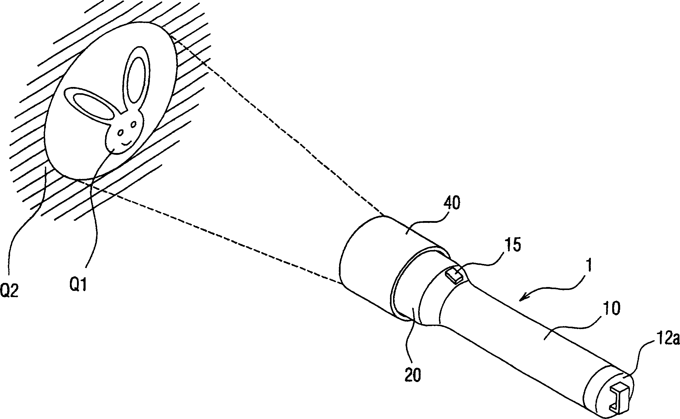
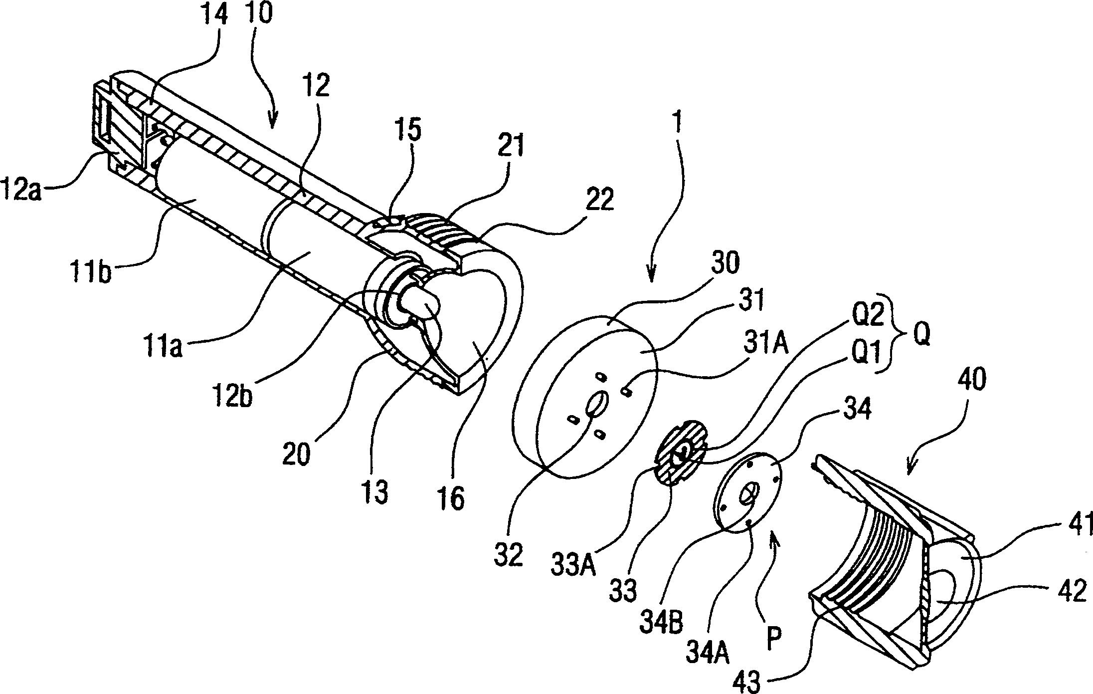
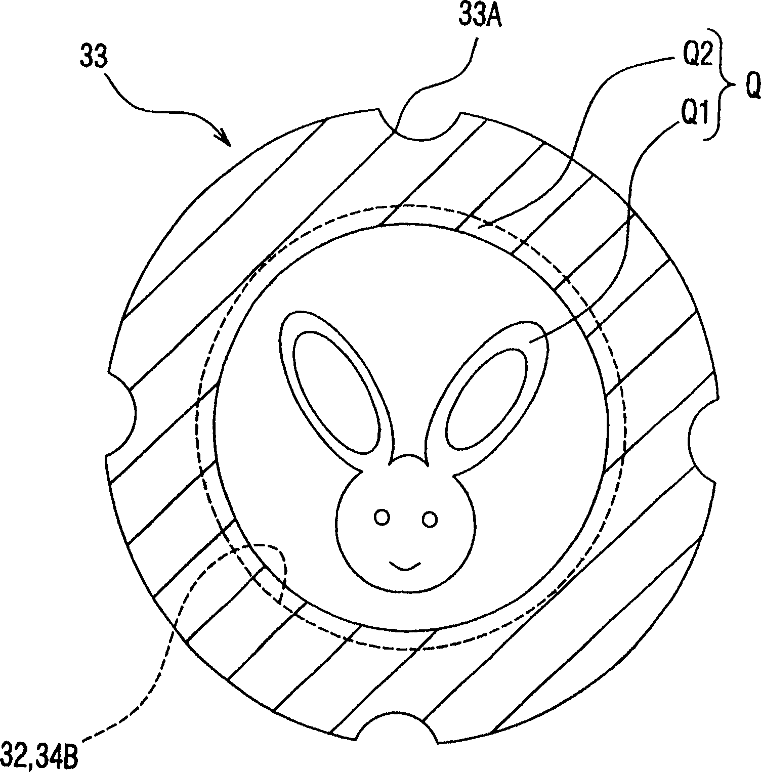
[0039] Figure 1-Figure 3 Reference numeral 1 of the first embodiment shown is a portable projection lighting device suitable for using batteries such as dry batteries, which can be used as lighting fixtures such as flashlights and advertising lighting, projection fixtures such as projection toys, and the like. The projection lighting device 1 itself is formed in a rod shape with a length from the rear end of the illuminator body 10 to the front end of the lens barrel 40, for example, about 20 cm.

[0040] The projection lighting device 1 such as figure 2 As shown, it is composed of an illuminator main body 10 , a shield frame portion 20 , a light shielding frame portion 30 and a lens barrel portion 40 . This illuminator main body 10 is made such as cylinder shape, uses as light source such as built-in battery 11a, 11b as dry cell to illuminate, and by the light of l...


PUM


Abstract

The present invention relates to a projection type lighting device and film component used therein. The device can easily form a clear silhouette having a distinct contour at the projected position by a lighted electric bulb. The present invention has a mask part 30, wherein a pattern with a inlay edge shape is composed by said Q2 part formed around inner surface patterns Q1 of the light transmission openings 32, simultantly the non-perspective display part Q2 is located at the inside circumference of the light transmission openings 32, and a film pressing means P is used to maintain a film member 33 at a light shielding plate 31 to the central part of the light transmission openings 32. The mask part 30 is detachably mounted to the front part of a hood casing part 20 formed on the lighting device main body 10. A cylindrical lens holder is mounted to the hood casing part 20 in a state of covering the whole part of the mask part. The film member 33 can be projected on a subscribed projection position by the light irradiated from the backside of the lighting device main body.

Description

technical field [0001] The present invention relates to a projection lighting device and a film member used therefor. The device is suitable for portability and can be used as a lighting device such as a flashlight and advertising lighting, a projection device such as a projection toy, etc., and can form a clear outline image on the projection position. Simple entertainment for children. Background technique [0002] In the past, as this kind of projection lighting device, the peripheral part of a film member printed with a pattern or the like was held by a rectangular or circular press frame, and the pattern printed on the film, etc. was displayed by an illumination device illuminated from the back of the press frame. Wait for the projection. [0003] However, in such a prior art projection lighting device, there is a problem that since light is transmitted through the film portion around the contour of the formed pattern, the contour shape of the pattern formed at the pro...

Claims


Application Information

Patent Timeline
IPC IPC(8): G02B27/18G03B21/14G03B21/20
Inventor 大藏光吉
Owner HALU
Why Eureka
Try Eureka