Sawtooth-shaped aircraft weapon cabin noise suppression device

A noise suppression and aircraft technology, applied in the aerospace field, can solve the problems of weakening the impact of the cabin, complexity, and destroying the aerodynamic shape of the aircraft, so as to improve the control effect, reduce the aerodynamic resistance, and achieve the best noise reduction effect

Active Publication Date: 2018-10-26
INST OF HIGH SPEED AERODYNAMICS OF CHINA AERODYNAMICS RES & DEV CENT
View PDF7 Cites 8 Cited by
  • Summary
  • Abstract
  • Description
  • Claims
  • Application Information

AI Technical Summary

Problems solved by technology

Active flow control changes the flow mode of airflow by installing jet or plasma devices inside and outside the cabin, thereby suppressing the generation of noise in the cavity. However, these devices are more complicated and have poor applicability; while passive flow control mainly uses Spoilers are installed on the front edge to change the position and speed of the shear layer in the cabin, weakening the impact on the cabin, so as to achieve the purpose of suppressing the noise in the cabin
[0004] Among them, installing sawtooth spoilers on the leading edge of the cabin is a simple and effective noise suppression method. However, while controlling the flow, the sawtooth structure also destroys the aerodynamic shape of the aircraft, thereby increasing the aerodynamic resistance of the aircraft.
In addition, studies have shown that when the height of the leading edge serrations is equal to the thickness of the incoming boundary layer at the leading edge of the cabin, the noise suppression effect in the cabin is the best, and the thickness of the incoming boundary layer is not the same under different flight conditions. Therefore, the existing Fixed-height sawtooths produce optimal noise reduction only under certain flight conditions

Method used


Image

  • Sawtooth-shaped aircraft weapon cabin noise suppression device
  • Sawtooth-shaped aircraft weapon cabin noise suppression device
  • Sawtooth-shaped aircraft weapon cabin noise suppression device

Examples


Embodiment 1

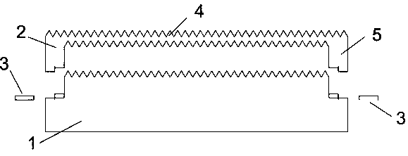
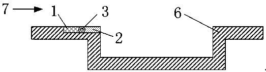
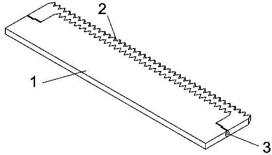
[0030] Such as figure 1 As shown, the spoiler in this example includes a bottom substrate and a spoiler. The spoiler is an inverted concave structure, and the bottom substrate is a convex structure. The overall width of the spoiler shown is w (slightly larger than the downstream cavity The width of ), the height is h (greater than the thickness of the maximum incoming boundary layer), and the thickness is d. The middle beam part of the spoiler has the same width as the downstream cavity. The upper and lower surfaces are both sawtooth structure, the tooth angle is 60°, the tooth height is 2mm, all the saw teeth are closely adjacent, the upper and lower edge of the sawtooth tip distance is about 0.3h, supported on both sides The width of the strip is about 5mm.

[0031] The substrate is a convex structure, the width is the same as the width of the spoiler, both are w, the total height is about 2h, and the thickness is d. The width of the protruding part is the same as that of the...


PUM


Abstract

The invention discloses a sawtooth-shaped aircraft weapon cabin noise suppression device. The device comprises a spoiler arranged on the front edge surface of a weapon cabin. The spoiler comprises a bottom face base plate and a spoiler sheet connected with the bottom face base plate. The spoiler sheet can rotate around the bottom face base plate through connecting points. The included angle between the rotating spoiler sheet and the bottom face base plate is any angle between 0 degree and 90 degrees. The upper surface and the lower surface of a crossbeam of the spoiler sheet are each of a sawtooth-shaped structure, and an incoming flow control effect can be greatly improved. The projected area of the device in the incoming flow normal direction is reduced through a gap in the bottom of thespoiler sheet, so that the aerodynamic drag of an aircraft is reduced. The inclination angle between the spoiler sheet and the base plate is changed, so that it is guaranteed that the height of the spoiler sheet is equivalent to the boundary layer thickness, and the best noise reduction effect on a downstream cabin can be achieved under different speed conditions.

Description

Technical field [0001] The invention relates to the field of aerospace technology, in particular to a sawtooth-shaped aircraft weapon bay noise suppression device. Background technique [0002] The built-in weapon bay is one of the main features of modern advanced fighters. The door is always closed when the fighter takes off / landing, cruises, etc., to maintain the fighter’s excellent aerodynamic shape, thereby reducing flight resistance, enhancing maneuverability, and enhancing stealth effect. When a fighter launches or releases weapons, the door of the weapon compartment is open, and the high-speed external airflow hits the rear wall of the weapon compartment, which will cause self-sustained oscillations in the compartment, thereby generating high-intensity aerodynamic noise in the compartment. The high-intensity noise environment not only fatigues the cabin structure and affects its service life, but also causes great harm to the health of equipment and personnel. [0003] At ...

Claims


Application Information

Patent Timeline
Patent Type & Authority Applications(China)
IPC IPC(8): B64C1/38B64C23/00
CPCB64C1/38B64C23/00
Inventor 周方奇王显圣杨党国刘俊施傲
Owner INST OF HIGH SPEED AERODYNAMICS OF CHINA AERODYNAMICS RES & DEV CENT
Why Eureka
Try Eureka