A kind of stripping device and stripping method

A technology for stripping and adjusting the device, applied in the directions of light guide, optics, instruments, etc., can solve the problems of easily damaged optical fiber, optical fiber burnout, uneven size of the incision, etc.

Active Publication Date: 2018-01-12
MAXPHOTONICS CORP
View PDF6 Cites 0 Cited by
  • Summary
  • Abstract
  • Description
  • Claims
  • Application Information

AI Technical Summary

Problems solved by technology

[0004] However, when using the above-mentioned device to strip the optical fiber, the length of the incision to be cut can only be measured according to the scale on the length direction of the pedestal, and the longitudinal depth of the incision cannot be quantitatively controlled, which often leads to uneven size of the incision. And if you don't pay attention, it is easy to damage the fiber
The optical fiber cut by the above-mentioned device is very easy to cause the local temperature of the optical fiber to be high due to the unevenness of the incision during use, which will cause the optical fiber to be burnt

Method used


Image

  • A kind of stripping device and stripping method
  • A kind of stripping device and stripping method
  • A kind of stripping device and stripping method

Examples


Embodiment Construction

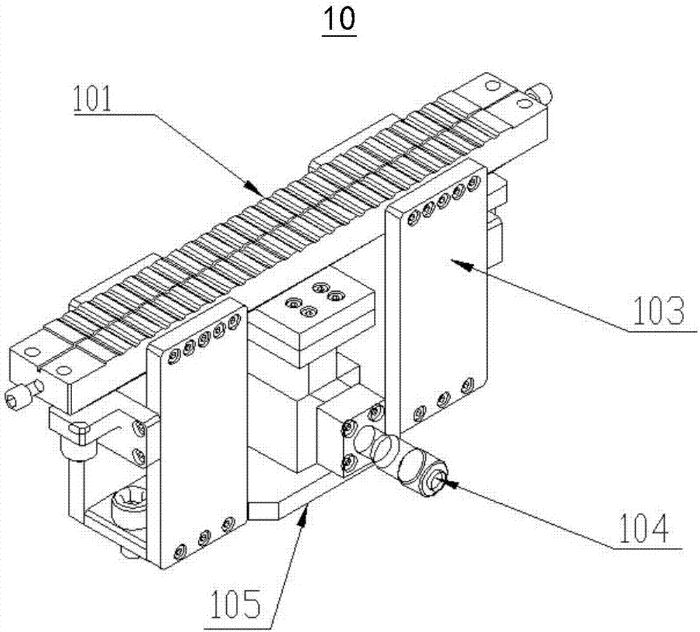
[0032] refer to figure 2 , the film stripper 10 includes: an optical fiber placement device 101, a stripping depth adjustment block (not shown), a fixed bracket 103, a displacement platform 104, and a base 105, wherein the fixed bracket 103 connects the optical fiber placement device 101 to the base 105 through the fixing device Connection, the stripping depth adjustment block and the displacement platform 104 are fixedly connected to form a supporting platform together to support, and are arranged in the inner space formed by the optical fiber placement device 101, the base 105 and the fixing device 103, the top surface of the base 105 and the displacement platform 104 is in contact with the bottom, and at the same time, the stripping depth adjustment block cooperates with the optical fiber placement device 101.

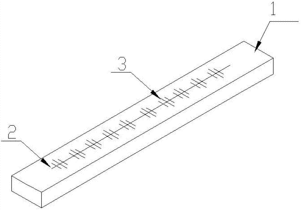
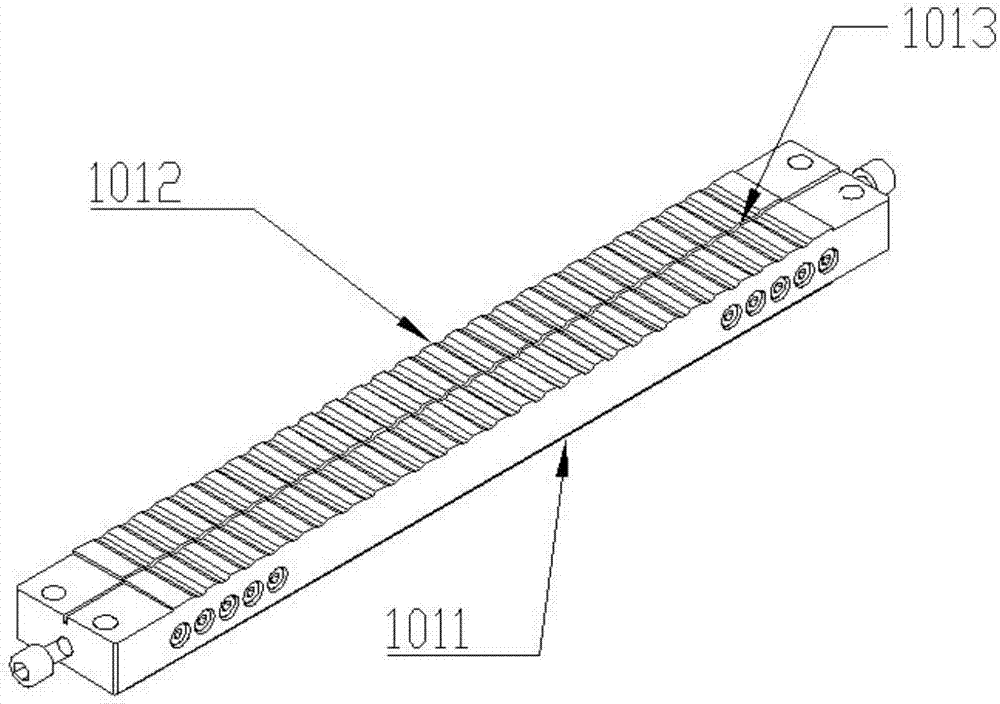
[0033] refer to image 3 , the optical fiber placement device 101 is in the shape of a cuboid as a whole and includes a base 1011 , at least one groove 1012 and a...


PUM


Abstract

The embodiment of the invention discloses a film peeling device, and the device comprises an optical fiber placing apparatus and a supporting platform. The optical fiber placing apparatus comprises a substrate, at least one groove, and at least one optical fiber placing groove. The groove and the optical fiber placing groove are placed on the substrate, and the groove is intersected with the optical fiber placing groove. The supporting platform and the optical fiber placing cooperate with each other. In the above mode, the device can cooperate with a mouth peeling depth adjustment block and a displacement platform for user because the optical fiber placing apparatus in the device is provided with at least one groove and at least one optical fiber placing groove. An adjustment rod for rotating the displacement platform drives a projection part on the mouth peeling depth adjustment block to move up and down. The device can cut a part, higher than the bottom of the groove, of an optical fiber placing in the optical fiber placing groove, and can accurately control the height of the part, higher than the groove, of the optical fiber.

Description

technical field [0001] The embodiments of the present invention relate to the technical field of fiber laser processing, in particular to an optical fiber stripping device and a stripping method. Background technique [0002] When the laser fiber is used, it is generally necessary to use a blade to cut a cut with a length of about 1.5mm-2mm on the fiber. The purpose is to make the pump light propagating from the inner cladding of the laser fiber naturally radiate to the outside world. [0003] Usually, the laser fiber is stripped by a stripper, such as figure 1 As shown, the traditional film stripper includes a pedestal 1, a center line 2, and a scale line 3. When in use, the optical fiber is placed on the center line 2 of the pedestal 1, and the optical fiber is fixed with a fixing device. The fiber is stripped to a specific length. [0004] However, when using the above-mentioned device to strip the optical fiber, the length of the incision to be cut can only be measured...

Claims


Application Information

Patent Timeline
Patent Type & Authority Patents(China)
IPC IPC(8): G02B6/245
CPCG02B6/245
Inventor 王辉蒋峰
Owner MAXPHOTONICS CORP
Why Eureka
Try Eureka