Display device

A technology for display devices and substrates, which is applied in nonlinear optics, instruments, optics, etc., and can solve the problems of lower yield and poor reworkability of flip chip flexible boards.

Active Publication Date: 2017-02-22
AU OPTRONICS CORP
View PDF5 Cites 14 Cited by
  • Summary
  • Abstract
  • Description
  • Claims
  • Application Information

AI Technical Summary

Problems solved by technology

In this way, not only will the yield rate of flip-chip FPC decrease, but also its reworkability may not be good.

Method used


Image

  • Display device
  • Display device
  • Display device

Examples


Embodiment Construction

[0089] A number of embodiments of the present invention will be disclosed in the following figures. For the sake of clarity, many practical details will be described together in the following description. It should be understood, however, that these practical details should not be used to limit the invention. That is, in some embodiments of the present invention, these practical details are unnecessary. In addition, for the sake of simplifying the drawings, some existing conventional structures and elements will be shown in a simple and schematic way in the drawings. For example, in each cross-sectional view, for clear illustration, some elements will be omitted from hatching.

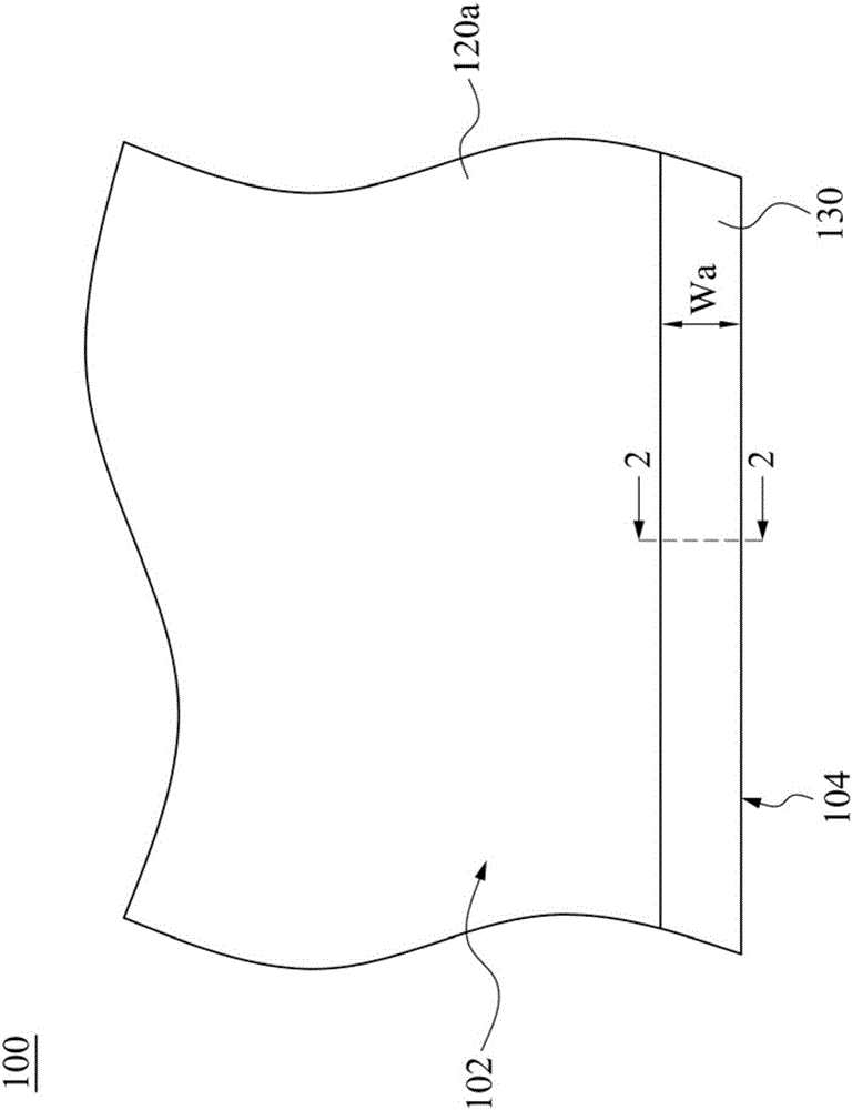
[0090] figure 1 A partial front view of a display device 100 according to an embodiment of the present invention is shown. As shown in the figure, the display device 100 has a display area 102 , which can also be called an active area (Active Area; AA), which is a range where a viewer can watch image...


PUM


Abstract

The invention discloses a display device comprising a first substrate, a first polarizing plate and a cover plate. The first polarizing plate is located on the first substrate so that a light passing through the first substrate can be emitted. The cover plate is at least partially located on the first substrate, and the cover plate extends in a direction away from the first polarizing plate and projects out of the first substrate. One side, opposite to the first substrate, of the cover plate is coplanar with one side, opposite to the first substrate, of the first polarizing plate.

Description

technical field [0001] The invention relates to a display device. Background technique [0002] The development of the frame of the display device has become more and more diverse. In the past, the development of the appearance of the display device was mainly towards the narrow bezel design, and various manufacturers are trying to reduce the area of ​​the decorative plate covering the display surface (ie, the surface facing the viewer). [0003] In recent years, display device manufacturers further hope to realize a full-plane display device with a frameless design. The display device has opposite left and right sides, and opposite upper and lower sides, wherein the upper side and the lower side can be called sky side and ground side respectively. Since the left and right sides and the sky side of the display device can be made using Gate On Array (GOA) technology, black colloid can be poured on the left, right and sky sides to replace the decorative plate. However, sinc...

Claims


Application Information

Patent Timeline
Patent Type & Authority Applications(China)
IPC IPC(8): G02F1/1333
CPCG02F1/1333G02F1/133308G02F1/133528G02F2202/28G02F1/13332
Inventor 简智伟吴志刚陈羣元蔡卲瑜薛芷苓
Owner AU OPTRONICS CORP
Why Eureka
Try Eureka