
LCD backlight module convenient to demount

A backlight module, a technology for easy disassembly, applied in optics, nonlinear optics, instruments, etc., can solve the problems of inconvenient disassembly, lower economic efficiency, and affect the efficiency of replacement and disassembly, so as to facilitate disassembly, improve work efficiency, and work efficiency Enhanced effect

Inactive Publication Date: 2017-02-22
李鑫
View PDF0 Cites 2 Cited by
  • Summary
  • Abstract
  • Description
  • Claims
  • Application Information

AI Technical Summary

Problems solved by technology

However, it is very inconvenient to disassemble the existing LCD backlight module, which seriously affects the efficiency of people's replacement and disassembly, thereby reducing economic efficiency, so it is extremely important to optimize its structure

Method used


Image

  • LCD backlight module convenient to demount
  • LCD backlight module convenient to demount
  • LCD backlight module convenient to demount

Examples


Embodiment 1

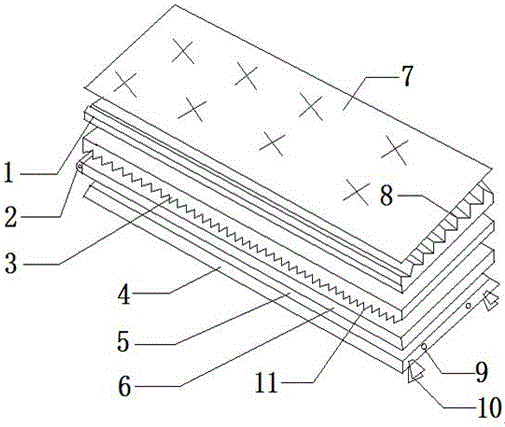
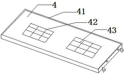
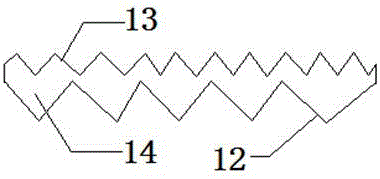
[0019] This example provides Figure 1-3 The LCD backlight module shown as a convenient disassembly includes a fixed base 4 and a reflective sheet 5, a light guide plate 6 is arranged above the reflective sheet 5, and a light emitting module 2 is installed on the left side of the light guide plate 6. The top of the light guide plate 6 is provided with a reverse-edge light-condensing sheet 3, and the bottom of the reverse-edge light-condensing sheet 3 is provided with a reverse-prism surface 11. A prism surface 8 is laid on the upper surface of the prismatic light concentrating sheet 1, an upper diffusion sheet 7 is arranged above the positive prismatic light concentrating sheet 1, and a through hole 9 is opened on the right side edge of the fixed base 4, and the left side of the through hole 9 A fixing clip 10 is provided, the fixing base 4 includes a heat dissipation window 42 , a protective pad 41 is arranged inside the fixing base 4 , and the heat dissipation window 42 is c...

Embodiment 2

[0022] This example provides Figure 1-3 The LCD backlight module shown as a convenient disassembly includes a fixed base 4 and a reflective sheet 5, a light guide plate 6 is arranged above the reflective sheet 5, and a light emitting module 2 is installed on the left side of the light guide plate 6. The top of the light guide plate 6 is provided with a reverse-edge light-condensing sheet 3, and the bottom of the reverse-edge light-condensing sheet 3 is provided with a reverse-prism surface 11. A prism surface 8 is laid on the upper surface of the prismatic light concentrating sheet 1, an upper diffusion sheet 7 is arranged above the positive prismatic light concentrating sheet 1, and a through hole 9 is opened on the right side edge of the fixed base 4, and the left side of the through hole 9 A fixing clip 10 is provided, the fixing base 4 includes a heat dissipation window 42 , a protective pad 41 is arranged inside the fixing base 4 , and the heat dissipation window 42 is c...


PUM


Abstract

The invention discloses an LCD backlight module convenient to demount. The LCD backlight module comprises a fixing base and a reflector. A light guide plate is arranged on the reflector. A light-emitting module is mounted on the left of the light guide plate. An inverse-edge light-condensation piece is arranged on the light guide plate. An inverse-edge mirror surface is mounted on the lower portion of the inverse-edge light-condensation piece. A forward-edge light-condensation piece is arranged on the inverse-edge light-condensation piece. A prism surface is laid on the upper surface of the forward-edge light-condensation piece. An upper diffuser is arranged on the forward-edge light-condensation piece. Through holes are formed in the right edge of the fixing base. A fixing clamp is arranged on the left of each through hole. The fixing base comprises radiating windows. The LCD backlight module has the advantages that the structure of the LCD backlight module is reasonable and perfect by adding new functions and overcoming original defects, an optimized effect can be achieved, the LCD backlight module can be demounted and mounted conveniently, and work efficiency of people is increased greatly.

Description

technical field [0001] The invention belongs to the technical field of backlight modules, and in particular relates to a conveniently disassembled LCD backlight module. Background technique [0002] The LCD backlight module is one of the key components of the LCD panel. The function is to supply sufficient brightness and evenly distributed light source so that it can display images normally. The so-called backlight is a light source located behind the liquid crystal display (LCD " "), and its luminous effect will directly affect the visual effect of the liquid crystal display module (LCM). Liquid crystal itself does not emit light, it displays graphics or characters as a result of its modulation of light. The development of backlight can be traced back to World War II. At that time, ultra-small tungsten filament lamps were used as backlights for aircraft instruments. This is the initial stage of backlight development. After half a century of development, backlight has b...

Claims


Application Information

Patent Timeline
Patent Type & Authority Applications(China)
IPC IPC(8): G02F1/13357
CPCG02F1/133606G02F1/133608G02F1/133607
Inventor 李鑫
Owner 李鑫
Learn More