Novel bearing chamber structure of motor

A bearing chamber, a new type of technology, applied in the direction of the casing/cover/support, electrical components, electromechanical devices, etc., can solve the problems of poor sealing performance, poor waste grease drainage, maintenance, inconvenience, etc., to achieve good sealing effect and reduce The probability of failure and the effect of facilitating on-site operation

Inactive Publication Date: 2017-02-22
CRRC YONGJI ELECTRIC CO LTD
View PDF9 Cites 9 Cited by
  • Summary
  • Abstract
  • Description
  • Claims
  • Application Information

AI Technical Summary

Problems solved by technology

[0003] The invention solves the problems of poor sealing performance of the existing motor bearing chamber structure, poor waste grease drainage and inconvenient maintenance, and provides a new type of motor bearing chamber structure

Method used


Image

  • Novel bearing chamber structure of motor
  • Novel bearing chamber structure of motor

Examples


Embodiment Construction

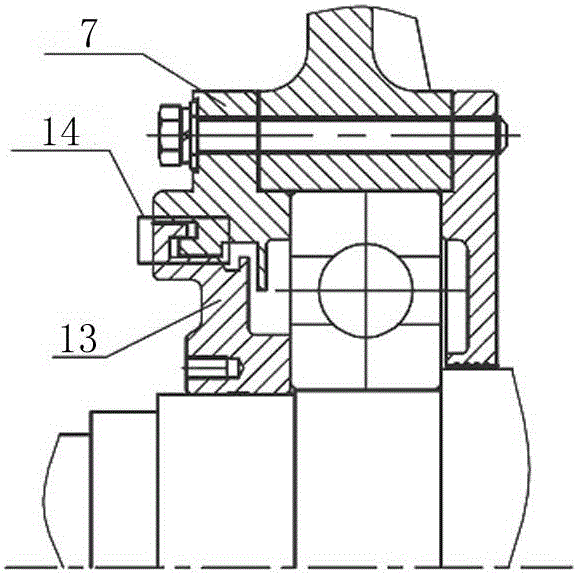
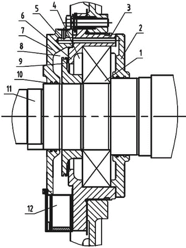
[0010] The new bearing chamber structure of the motor includes an inner bearing cover 2, an end cover 3, and an outer bearing cover 7. The outer bearing cover 7 is provided with an oil injection hole, and the end cover 3 is provided with an inner bearing cover 2 connected to the oil injection hole. The lubricating channel 5 on the side, the lubricating channel 5 communicates with the inner bearing chamber, that is, the space between the inner end cover and the bearing, and the bearing hole of the end cover 3 radially extends out of the oil deflector ring 6 toward the outer bearing cover 7 side, and the retainer The inner diameter of the oil ring 6 is equal to or approximately equal to the average diameter of the bearing 1, so that the lubricating grease inside the bearing will not be lost quickly, and its components are fully lubricated; an oil storage chamber is formed between the oil retaining ring 6 and the bearing 1 4. The side of the oil deflecting ring 6 facing the outer ...


PUM


Abstract

The invention relates to a bearing chamber structure of a motor, particularly relates to a novel bearing chamber structure of the motor and aims to solve problems of poor airtightness, difficulty in waste grease discharge and inconvenience in maintenance of an existing motor bearing chamber structure. The scheme includes that an outer bearing cover is provided with an oil injection hole, an end cover is provided with a lubrication passage, and the end cover radially extends towards one side of the outer bearing cover to extend out of an oil retainer. An oil storage cavity is formed between the oil retainer and a bearing, and an oil flinger is arranged on one side, facing the outer bearing cover, of the oil retainer. An oil flinging gap is reserved between the oil flinger and the oil retainer, and a waste oil discharge chamber is formed between the oil flinger and the outer bearing cover. An oil collector communicated with the waste oil discharge chamber is arranged on the lower portion of the outer bearing cover. The novel chamber structure of the motor has advantages that firstly, quick loss of lubricating grease in the bearing is prevented, and complete lubrication of the bearing is guaranteed; secondly, smoothness and timeliness in discharge of waste grease and excessive lubricating grease are realized; thirdly, excellent sealing effects are achieved, so that the lubricating grease is protected from pollution; fourthly, the oil collector is convenient to demount, and the requirement on regular maintenance of waste grease is met.

Description

technical field [0001] The invention relates to a motor bearing chamber structure, in particular to a bearing chamber structure of a doubly-fed wind power generator, an AC synchronous generator, an asynchronous motor and the like, which require bearing relubrication, and in particular to a new type of motor bearing chamber structure. Background technique [0002] In the fault category of motors, bearing faults account for a large proportion, and the cause of most bearing failures is poor lubrication, including poor oil lubrication, transitional lubrication, grease pollution, and poor drainage of waste grease. Noise, wear, sticking, galling, fatigue failure and overheating, etc. The commonly used bearing chamber structure of existing motors is as follows: figure 1 As shown, a sealed cavity 14 is formed between the outer bearing cover 7 and the sealing ring 13, and the outer bearing cover 7, the sealing ring 13 and the bearing 1 form a single lubricating cavity. This kind of ...

Claims


Application Information

Patent Timeline
Patent Type & Authority Applications(China)
IPC IPC(8): H02K5/16
CPCH02K5/16
Inventor 张广兴黄熙
Owner CRRC YONGJI ELECTRIC CO LTD
Why Eureka
Try Eureka