Main controller, electric cabinet having same and method for connecting main controller and loads
A main controller and wiring technology, applied to the circuit layout, electrical components, chassis/cabinet/drawer parts, etc. on the support structure, which can solve the crowded electric control box, low wiring efficiency, electrical accidents, etc. problems, to save man-hours, improve wiring efficiency, and reduce inaccurate wiring
- Summary
- Abstract
- Description
- Claims
- Application Information
AI Technical Summary
Problems solved by technology
Method used
Image

Examples
Embodiment 1
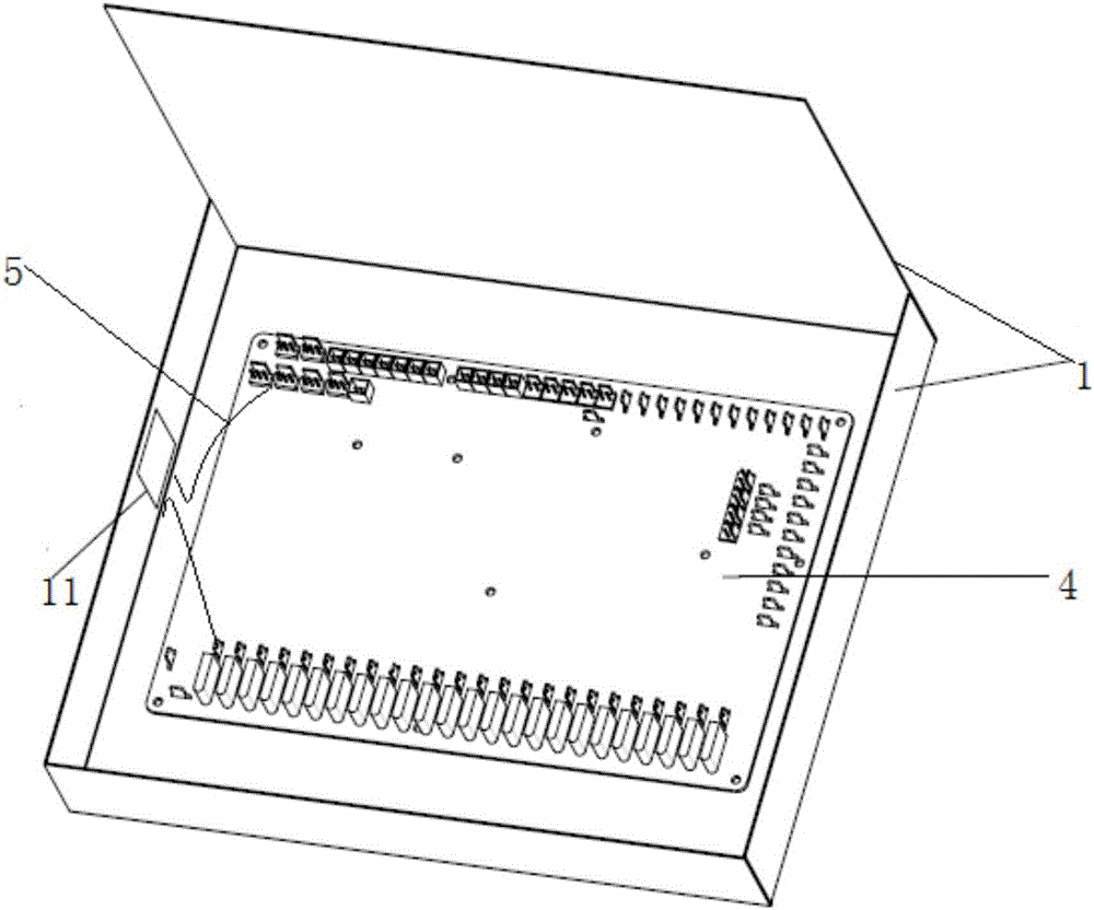
[0062] This embodiment provides a main controller 9, including
[0063] The box body 1 is provided with mounting holes 11 on its side wall, such as figure 1 shown;
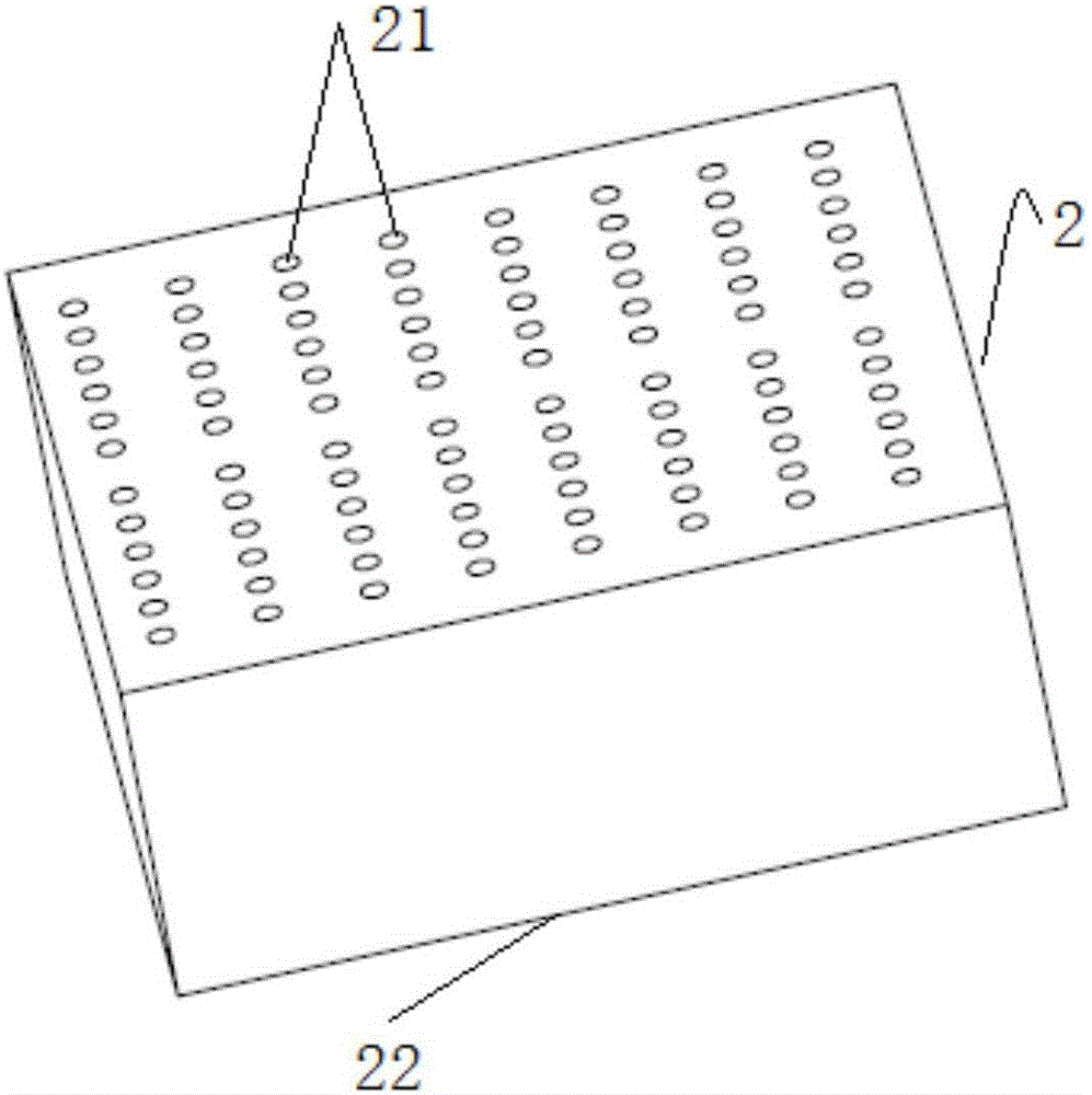
[0064] The female terminal 2 is installed on the side wall of the box body 1 through the installation hole 11, such as figure 2 As shown, the female terminal has a female terminal connection part 21 and a female terminal connection part 22, the female terminal connection part 21 is located inside the box body 1, and the female terminal connection part 2 is located outside the box body 1;
[0065] The main board 4 is packaged inside the box body 1;
[0066] There are several internal wires 5, one end of which is connected to the main board 5, and the other end is connected to the female terminal wiring part 21; and
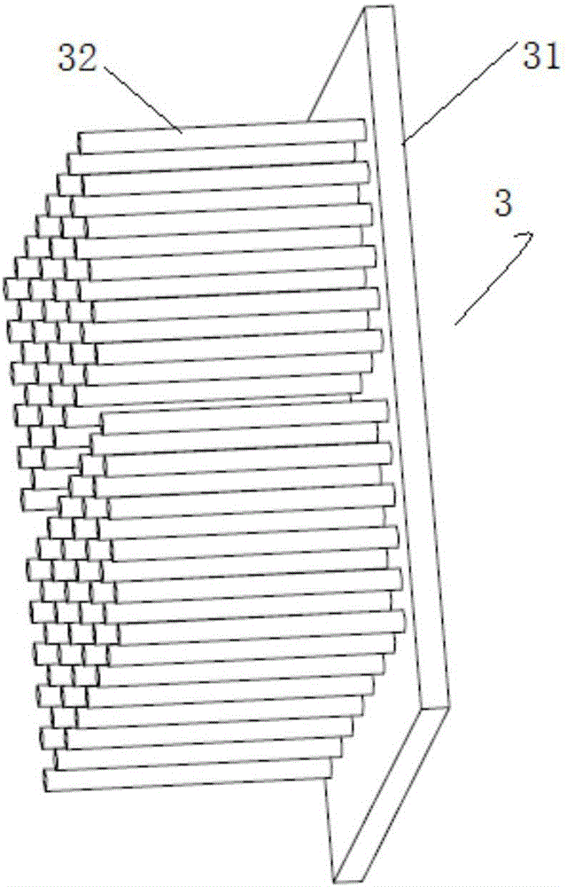
[0067] The male terminal 3 is located outside the box body 1, such as image 3 As shown, it has a male terminal connection part 31 and a male terminal connection part 32 , and is detachably elect...
Embodiment 2
[0079] This embodiment provides an electric control box, such as Figure 4 As shown, it includes a box body 7; the main controller 9 is the main controller 9 described in the above-mentioned embodiment (the main controller itself does not integrate external wires); the wiring trough 8 is arranged in the box body 7 and is located at The outside of the main controller 9; the external wires 6 are several (only one is shown in the figure), one end of which is connected to the public terminal wiring part 31, and the other end passes through the wire slot 8 and stretches out the Box 7.
[0080] The electric control box, because it adopts the above-mentioned main controller 9, has the advantages of any one of the main controller 9 described in the above-mentioned implementation.
[0081] As a preferred embodiment, the wiring trough 8 and the male terminal 3 are located on the same side of the box body 1, such a structural design facilitates the centralized routing of the external wi...
Embodiment 3
[0084] This embodiment provides a wiring method between the main controller and the load, including the following steps:
[0085] S1: one end of the internal wire 5 is electrically connected to the main board 4;
[0086] S2: electrically connect the other end of the internal wire 5 to the female terminal connection part 21 of the female terminal 2;
[0087] S3: electrically connect the external wire 6 to the load 10;
[0088] S4: electrically connect the external wire 6 to the male terminal connection portion 31 of the male terminal 3;
[0089] S5: Connect the male terminal 32 of the male terminal 3 to the female terminal 22 of the female terminal 2 to realize the electrical connection between the male terminal 3 and the female terminal 2 .
[0090] The above-mentioned wiring method between the main controller 9 and the load 10 breaks the idea in the prior art that the internal wire 5 of the main controller 9 directly extends out of the main controller 9 for connection, and ...
PUM
 Abstract
Description
Claims
Application Information
 - Generate Ideas
- Intellectual Property
- Life Sciences
- Materials
- Tech Scout
- Unparalleled Data Quality
- Higher Quality Content
- 60% Fewer Hallucinations
Browse by: Latest US Patents, China's latest patents, Technical Efficacy Thesaurus, Application Domain, Technology Topic, Popular Technical Reports.
© 2025 PatSnap. All rights reserved.Legal|Privacy policy|Modern Slavery Act Transparency Statement|Sitemap|About US| Contact US: help@patsnap.com