
Laterally-expanding tray table

A tray table, horizontal technology, applied in special positions of vehicles, chairs, cabin crew accommodation, etc.

Inactive Publication Date: 2017-02-22
BE AEROSPACE INCORPORATED
View PDF6 Cites 3 Cited by
  • Summary
  • Abstract
  • Description
  • Claims
  • Application Information

AI Technical Summary

Problems solved by technology

So items such as personal electronic devices or IFE controllers can more easily occupy this extra space

Method used


Image

  • Laterally-expanding tray table
  • Laterally-expanding tray table
  • Laterally-expanding tray table

Examples


Embodiment Construction

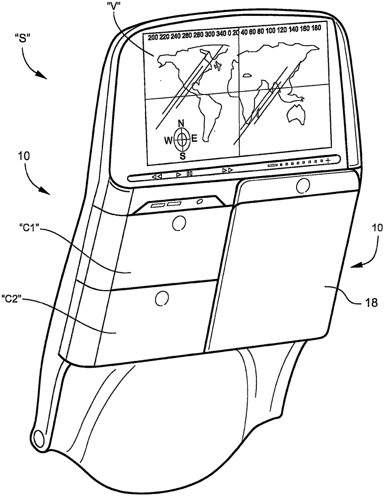
[0029] now refer to figure 1 , which shows a typical type of seat back "S" based on the main and business class areas of commercial aircraft, to which a tray table 10 is mounted according to one embodiment of the present invention. As shown, the first table segment 18 in its stowed position occupies one side of the rear of the seat back "S", leaving the other side for accommodating IFE or other occupant convenience features "C1" and "C2". side. As also shown, the seat back "S" is provided with a video monitor "V" that includes a reverse, playback , pause / stop, fast forward and volume control.

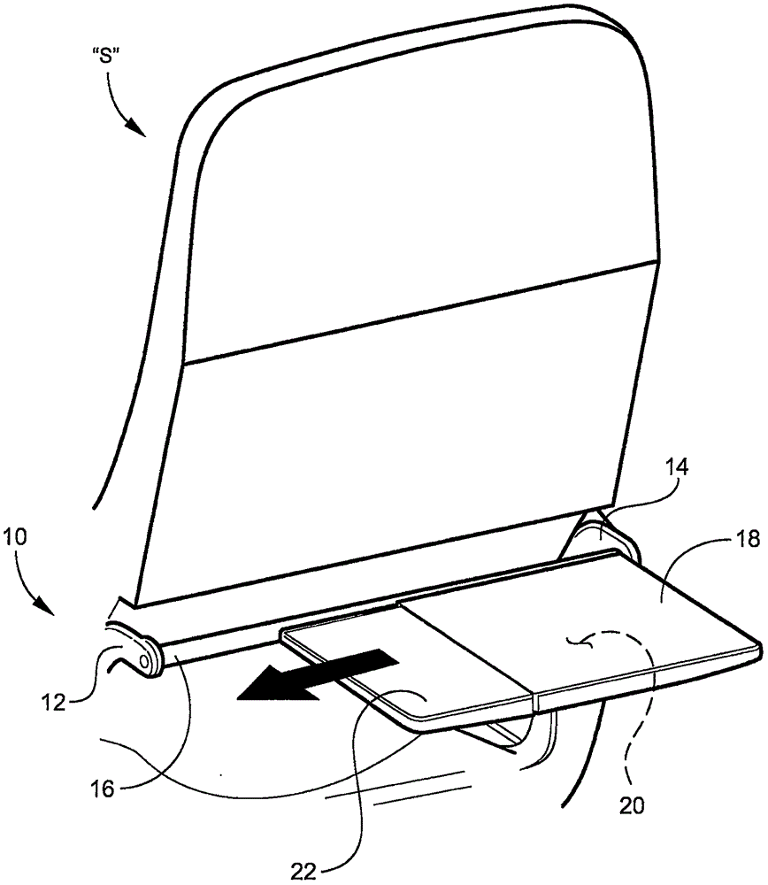
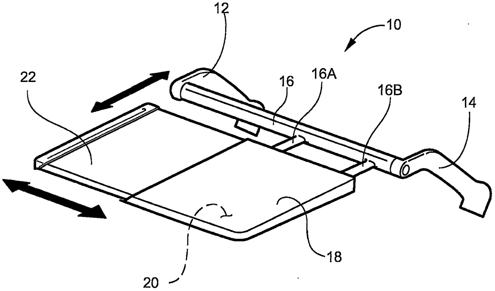
[0030] under the Figure 2 to Figure 5 In , the video monitor "V" and convenience features "C1" and "C2" have been removed for clarity in describing and illustrating tray table 10.

[0031] now refer to figure 2 with image 3 , the tray table 10 includes an arm assembly having a pair of laterally opposed arms 12, 14 connected by a pivotally mounted stabilizing crossbar 16. Such ...


PUM


Abstract

A seat back tray table that includes an arm assembly attached to a seat having a seat back, and moveable between a stowed position and a deployed, use position, a first table segment carried by the arm assembly and moveable with the arm assembly between a stowed position against a stowage area of the seat back and a deployed position aft of the stowage area, and a second table segment carried by the first table segment and moveable between a stored position within the stowage area of the seat back and a deployed position laterally extended from the first table segment to increase the total surface area of the tray table.

Description

[0001] Priority claims and cross-references to earlier-filed applications [0002] This application claims priority to US Provisional Patent Application Serial No. 61 / 976,212, filed April 7, 2014, the entire contents of which are incorporated herein by reference. technical field [0003] The present invention relates to tray tables based on the type of transportation seating products such as railway seats and aircraft passenger seats. Existing tray tables typically extend the width of the seat back and are movable between a stowed position that is flush with and latched to the seat back of the seat, and a deployed position, with the tray table away from the seat back. The seat back extends to a generally horizontal position for an occupant seated behind. Other prior art seats include a double-folding tray table that is hinged in the middle and is usually stowed in the armrests in a folded configuration. To deploy the table, the arm cap is raised, the table pivots out of the ...

Claims


Application Information

Patent Timeline
IPC IPC(8): A47C7/70
CPCB64D11/0638B60N3/004B64D11/00151
Inventor B·D·斯蒂芬斯M·A·克鲁斯F·X·加林
Owner BE AEROSPACE INCORPORATED
Learn More