Drag chain

A technology of energy and chains, applied in the direction of drag chains, hanging chains, electrical components, etc., can solve the problem that harmful foreign objects cannot be easily pasted

Active Publication Date: 2017-02-22
IGUS
View PDF5 Cites 3 Cited by
  • Summary
  • Abstract
  • Description
  • Claims
  • Application Information

AI Technical Summary

Problems solved by technology

Thanks to this curvature of the individual wall areas it is already very effectively ensured

Method used


Image

  • Drag chain
  • Drag chain
  • Drag chain

Examples


Embodiment Construction

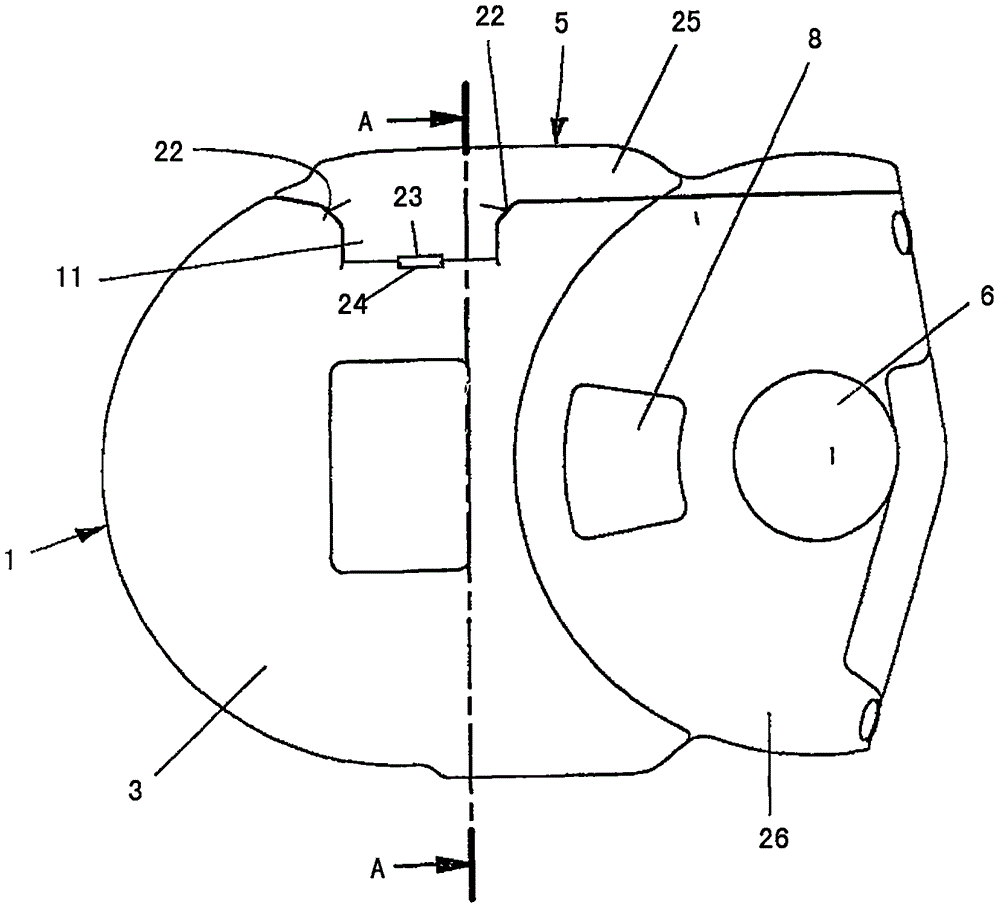
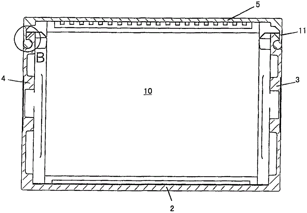
[0033] Figure 1 to Figure 12 An embodiment of an energy guiding chain according to the invention for guiding cables, hose-like items (cables, hoses, etc. items) between two connection points moving relative to each other is shown. This energy guiding chain comprises a plurality of tubular links 1 connected to each other in an articulated manner and made of plastic, and each tubular link 1 has a bottom wall 2, adjoining opposite side walls 3, 4 and cover wall 5.

[0034] In the embodiment shown in the figures, the bottom wall 2 and the side walls 3, 4 are of one-piece design, while the cover wall 5 is detachably connected to the side walls.

[0035] According to a further embodiment (not shown in the drawings), of course, the bottom wall 2 can optionally also be made detachable.

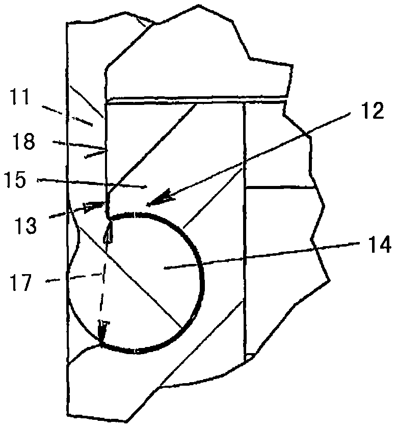
[0036] In particular, as can be seen from FIG. 6 , the side walls 3 , 4 each have a pivot pin 6 on its outside and a coupling opening 7 on the inside at a distance from said pivot pin 6 . The pivo...


PUM


Abstract

The invention relates to a drag chain for guiding cables, hoses, and the like between two connection points that can be moved in relation to each other, comprising a plurality of tubular chain links (1), which are articulated to each other and are made from plastic. The chain links each have a bottom wall (2), opposite side walls (3) adjoining the bottom wall, and a cover wall (5). The cover wall (5) is or can be removably connected to the side walls (3, 4). The side walls (3, 4) each have a joint pin (6) and a joint opening (7) for the articulation of adjacent chain links (1). The pivot angle is limited in both pivot directions by stops (8). The cover walls (5), side walls (3, 4), and bottom walls (2) overlap over the entire pivoting angle.

Description

technical field [0001] The invention relates to an energy-guiding chain (traction chain) for guiding cables, hose-like items (cables, hoses, etc.) between two connection points moving relative to each other, which includes a plurality of tubular links hingedly connected to one another and made of plastic, and each tubular link has a bottom wall, adjoining opposing side walls, and a cover wall, wherein the cover wall is or can be detachably connected to said side walls, said side walls each having a pivot pin and a coupling port for hinged connection with an adjacent link, by stops in both pivot directions to limit the pivot angle, and the cover walls, side walls and bottom walls of adjacent links overlap over the entire pivot angle. Background technique [0002] Such energy chains, which are largely closed over their entire circumference, are used in particular in environments where there is a risk of foreign objects entering the chain, for example on metal-cutting machine ...

Claims


Application Information

Patent Timeline
IPC IPC(8): F16G13/16H02G11/00H02G3/04
CPCF16G13/16H02G3/0475H02G11/00H02G3/0456
Inventor T-A·耶克尔D·巴腾J·多姆尼克
Owner IGUS
Why Eureka
Try Eureka