Live working method of power distribution equipment

A technology of live work and power distribution equipment, applied in the installation of overhead lines/cable equipment, electrical components, cables, etc.

Active Publication Date: 2018-09-07
曙光电子通讯工程(株) +1
View PDF7 Cites 0 Cited by
  • Summary
  • Abstract
  • Description
  • Claims
  • Application Information

AI Technical Summary

Problems solved by technology

[0004] These jobs are to move the live wires up and down, left and right, so there are certain safety risks

Method used


Image

  • Live working method of power distribution equipment
  • Live working method of power distribution equipment
  • Live working method of power distribution equipment

Examples


Embodiment Construction

[0040] The specific content of implementing the invention

[0041] Referring to the drawings in the appendix, the embodiment of the live working method for power distribution equipment of the present invention is described. In this process, the thickness of the lines or the size of the components in the drawing may be exaggerated for the sake of clarity.

[0042] The terms described below are defined in consideration of the functions in the present invention, and may vary depending on the user's or operator's intention or practice. Therefore, these terms should be defined based on the overall content of this specification.

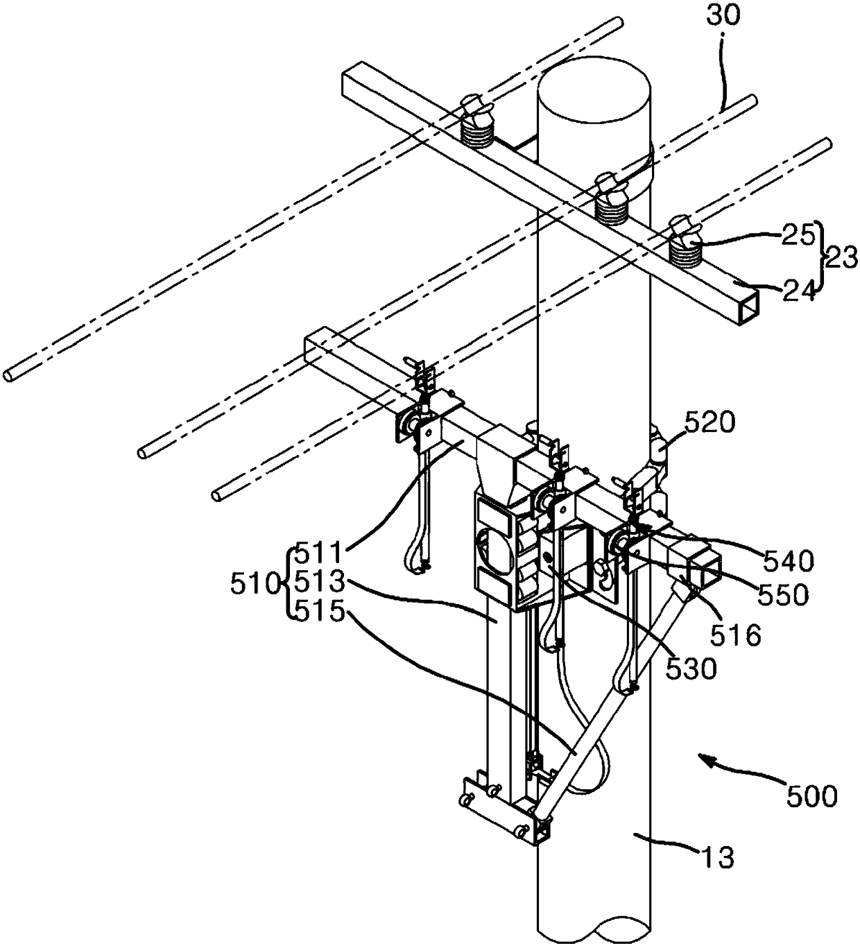
[0043] First, the assisting device 500 for live work of electric power distribution equipment according to the present invention will be described.

[0044] figure 1 It is a schematic perspective view of an auxiliary device for live working of power distribution equipment according to an embodiment of the present invention.

[0045] refer to figure 1 ...


PUM


Abstract

A power distribution facility live-line working method of the present invention comprises the steps of: fixing an temporary arm part to an electric pole; transferring an electric wire connected to the electric pole to an electric wire support part provided on the temporary arm part; by moving the temporary arm part or the electric wire support part upward, separating the electric wire from an existing LP insulator pre-installed on a pin crossarm; moving, in a separating direction from the electric pole, at least one of a plurality of electric wire support parts having electric wires transferred thereto; removing the existing LP insulator installed on the pin crossarm; installing a new LP insulator on the pin crossarm; by moving, in the direction of the electric pole, the at least one of the plurality of electric wire support parts moved in a separating direction from the electric pole, bringing the at least one of the plurality of electric wire support parts close to the new LP insulator; and transferring the electric wire from the electric wire support part to the new LP insulator.

Description

technical field [0001] The present invention relates to the related content of the live working method of the power distribution equipment, and relates to the content of setting up a new utility pole by using an auxiliary device for the live work of the power distribution equipment. Background technique [0002] A cross arm is generally installed on the top of the utility pole, and the cross arm is composed of a horizontal iron cross arm and three insulators installed on the iron cross arm. The 3-phase wires are respectively connected to the 3 insulators by adhesive. [0003] When maintaining installed utility poles, cross-arms, and insulators, replace old insulators with new insulators, replace old cross-arms with new ones, replace old ones with new poles, or extend the angle of wires caused by changes in the position of utility poles Due to the increase and other reasons, there are operations such as replacing the PIN cross-arm with the inner cross-arm. There is also wor...

Claims


Application Information

Patent Timeline
Patent Type & Authority Patents(China)
IPC IPC(8): H02G7/00H02G1/02
CPCE04H12/24E04H12/34H01B17/16H02G1/02H02G7/02H02G7/05H02G7/205
Inventor 崔敏洙
Owner 曙光电子通讯工程(株)
Why Eureka
Try Eureka