DMRS (demodulation reference signal) indication method, system, base station and user equipment

An indication and base station technology, applied in the field of systems, base stations and user equipment, and demodulation reference signal indication methods

Active Publication Date: 2017-03-01
CHINA MOBILE COMM GRP CO LTD
View PDF6 Cites 37 Cited by
  • Summary
  • Abstract
  • Description
  • Claims
  • Application Information

AI Technical Summary

Problems solved by technology

[0003] However, in the context of no major breakthroughs in physical layer technology, how to further improve the spectral efficiency of wireless communication systems is a hot research issue

Method used


Image

  • DMRS (demodulation reference signal) indication method, system, base station and user equipment
  • DMRS (demodulation reference signal) indication method, system, base station and user equipment
  • DMRS (demodulation reference signal) indication method, system, base station and user equipment

Examples


Embodiment 1

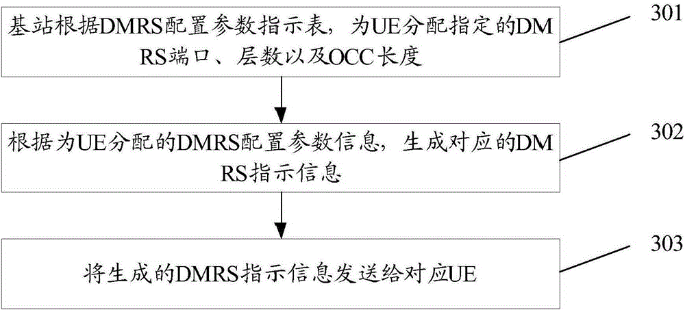
[0135] This embodiment provides a DMRS indication method, which is applied to a base station, such as image 3 As shown, the method includes the following steps:

[0136] Step 301: the base station allocates a specified DMRS port, layer number and OCC length for the UE according to the DMRS configuration parameter indication table;

[0137] Here, the DMRS configuration parameter indication table records various DMRS configuration parameter indication entries of combinations of various OCC lengths with at least two OCC lengths.

[0138] Wherein, the lengths of the at least two OCCs may be 2 and 4, respectively.

[0139] When the DMRS port, the number of layers and the OCC length specified for the UE are allocated, the method may also include:

[0140] Allocating a specified scrambling code ID to the UE according to the DMRS configuration parameter indication table.

[0141] Various DMRS configuration parameter indication entries for single codeword transmission include: sing...

Embodiment 2

[0214] The DMRS indication method of this embodiment is applied to a base station. The application scenarios of this method are: the maximum number of total user data streams to be transmitted is 8; the maximum number of data streams per user during multi-user transmission is 2; The maximum number is 4; if Figure 7 As shown, the method includes the following steps:

[0215] Step 701: the base station allocates corresponding DMRS configuration parameters for the UE;

[0216] Here, in this embodiment, an OCC with a length of 4 is used as the OCC.

[0217] Step 702: Generate corresponding DMRS indication information, where the DMRS indication information is 3 bits;

[0218] Here, the DMRS indication information is used to indicate the DMRS configuration parameter information allocated for the UE.

[0219] Wherein, the DMRS indication information may be carried in DCI.

[0220] When using the DMRS indication shown in Table 4, it is necessary to use 4 bits in the DCI for indic...

Embodiment 3

[0276] In order to implement the method in Embodiment 1, this embodiment provides a base station, such as Figure 10 As shown, the base station includes: a first allocation unit 101, a first generation unit 102, and a first sending unit 103; wherein,

[0277] The first allocation unit 101 is configured to allocate a specified DMRS port, layer number, and OCC length for the UE according to the DMRS configuration parameter indication table; various OCCs with at least two OCC lengths are recorded in the DMRS configuration parameter indication table A variety of DMRS configuration parameter indication entries with length combinations;

[0278] The first generating unit 102 is configured to generate corresponding DMRS indication information according to the DMRS configuration parameter information allocated for the UE;

[0279] The first sending unit 103 is configured to send the generated DMRS indication information to a corresponding UE.

[0280] Wherein, the lengths of the at ...


PUM


Abstract

The present invention discloses a DMRS (demodulation reference signal) indication method. The method includes the following steps that: designated DMRS ports, layers and orthogonal cover code (OCC) lengths are assigned to user equipment (UE) according to a DMRS configuration parameter indication table; various kinds of DMRS configuration parameter indication entries of various kinds of OCC length combinations containing at least two OCC lengths are recorded in the DMRS configuration parameter indication table; and corresponding DMRS indication information is generated according to the DMRS configuration parameter information assigned to the UE, and the corresponding DMRS indication information is sent to the UE. The present invention also discloses a base station, UE (user equipment) and a DMRS (demodulation reference signal) indication system.

Description

technical field [0001] The present invention relates to the field of wireless communication, in particular to a demodulation reference signal (DMRS, DeModulation Reference Signal) indication method, system, base station and user equipment (User Equipment). Background technique [0002] Existing communication systems (such as Long Term Evolution (LTE, Long Term Evolution) system, Worldwide Interoperability for Microwave Access (WiMax, Worldwide Interoperability for Microwave Access) system, wireless local area network (WLAN, Wireless Local Area Networks) system using the 802.11n standard, etc. ) adopt the traditional two-dimensional 2D multiple-input multiple-output (MIMO, Multiple-Input Multiple-Output) technology, the basic principle of which is to use the two-dimensional spatial freedom of the antenna on the horizontal plane to improve the transmission quality and increase the system capacity. [0003] However, under the background that there is no major breakthrough in th...

Claims


Application Information

Patent Timeline
Patent Type & Authority Applications(China)
IPC IPC(8): H04L1/00H04B7/0413
CPCH04B7/0452H04L1/0026H04L27/2613H04L1/16H04W24/10H04L5/0053H04L5/0091H04L5/0051H04W72/23
Inventor 金婧童辉王飞王启星
Owner CHINA MOBILE COMM GRP CO LTD
Why Eureka
Try Eureka