Temperature superposition type high-temperature industrial television controller

A high-temperature industrial controller technology, applied in the field of temperature-superimposed high-temperature industrial TV controllers, can solve problems such as energy consumption and the inability to see temperature changes in real time, and achieve the effect of reducing maintenance costs

Pending Publication Date: 2017-03-01
常州宝仪机电设备有限公司
4 Cites 0 Cited by

AI-Extracted Technical Summary

Problems solved by technology

[0002] The traditional monitoring method of industrial kiln is high-temperature industrial TV plus infrared thermometer. Two sets of systems are completed independently, which requires two sets of protective equipment and water and gas pipelines, which will consume double the energy.
In order to protect the safety of operating eq...

Abstract

The invention discloses a temperature superposition type high-temperature industrial television controller, which comprises a thermocouple temperature superposition structure, an infrared thermometer temperature superposition structure, a camera, an automatic advance and retreat control structure and a controller, wherein the internal part of the camera is provided with the thermocouple temperature superposition structure and the infrared thermometer temperature superposition structure, the camera is connected with the controller, and the camera is provided with the automatic advance and retreat control structure. According to the above mode, the temperature superposition type high-temperature industrial television controller is simple in structure, can detect the temperature of the camera and the temperature of a material at the same time, not only guarantees the safety of the equipment itself, but also can provide an actual hotbed of a target object.

Application Domain

Radiation pyrometryClosed circuit television systems

Technology Topic

EngineeringHotbed +4

Image

  • Temperature superposition type high-temperature industrial television controller
  • Temperature superposition type high-temperature industrial television controller

Examples

  • Experimental program(1)

Example Embodiment

[0015] The technical solutions in the embodiments of the present invention will be described clearly and completely below. Obviously, the described embodiments are only a part of the embodiments of the present invention, rather than all the embodiments. Based on the embodiments of the present invention, all other embodiments obtained by those of ordinary skill in the art without creative work shall fall within the protection scope of the present invention.
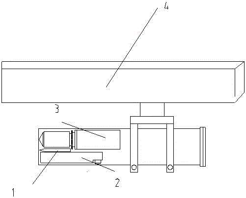
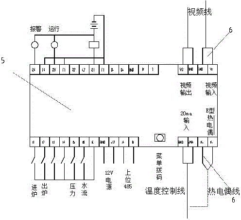
[0016] See figure 1 with figure 2 , The embodiment of the present invention includes:
[0017] A temperature superimposition type high temperature industrial television controller, including: thermocouple temperature superposition structure 1, infrared thermometer temperature superposition structure 2, camera 3, automatic advance and retreat control structure 4 and controller 5, the camera 3 is provided with The thermocouple temperature superimposition structure 1 and the infrared thermometer temperature superimposition structure 2. The camera 3 is connected to the controller 5, and the camera 3 is provided with an automatic advance and retreat control structure 4.
[0018] In addition, the thermocouple temperature superposition structure 1 is connected to the controller 5 through a thermocouple wire.
[0019] In addition, the temperature superposition structure 2 of the infrared thermometer is connected to the controller 5 through a temperature control line.
[0020] In addition, the controller 5 outputs the detected temperature to the monitor through the video transmission cable, and the monitor screen displays the temperature mode: the thermocouple value at the upper left and the infrared thermometer value at the upper right.
[0021] In addition, the controller 5 is provided with a remote communication interface module 6 for connecting the camera 3 and the monitor.
[0022] The temperature superimposition type high temperature industrial television controller of the present invention. When working, the controller 5 superimposes the real-time monitoring of the internal cavity temperature data of the camera 3 onto the video line and visually displays it on the upper left of the monitor, and can set the internal cavity alarm temperature , To prevent the camera 3 from burning out; at the same time, the temperature data of the flame or material is superimposed on the video line and displayed on the upper right of the monitor, which not only ensures the safety of the equipment itself, but also provides an actual hotbed for the target object. The staff can operate the buttons on the controller menu, or control the camera control unit in the control cabinet through the computer in the main control room, so as to control the menu control items of the camera 3 and the infrared thermometer, without the need for the camera 3 with higher temperature. And infrared thermometer end controller menu control items, so the function of remotely adjusting the menu control items of the camera when the industrial furnace camera is working normally, has the characteristics of high security and convenient control.
[0023] The above are only the embodiments of the present invention and do not therefore limit the scope of the present invention. Any equivalent structure or equivalent process transformation made by using the content of the present invention description, or directly or indirectly applied in other related technical fields, are all The same reason is included in the scope of patent protection of the present invention.

PUM

no PUM

Description & Claims & Application Information

We can also present the details of the Description, Claims and Application information to help users get a comprehensive understanding of the technical details of the patent, such as background art, summary of invention, brief description of drawings, description of embodiments, and other original content. On the other hand, users can also determine the specific scope of protection of the technology through the list of claims; as well as understand the changes in the life cycle of the technology with the presentation of the patent timeline. Login to view more.

Similar technology patents

Permanent magnet linear synchronous motor system with low thrust fluctuation and parameter design method of system

InactiveCN103227552AImprove dynamic performanceReduce maintenance costs
Owner:NANJING UNIV OF AERONAUTICS & ASTRONAUTICS

Classification and recommendation of technical efficacy words

  • Reduce maintenance costs

Automatic deployment system and method of hadoop cluster

ActiveCN103064742ASimple frame structureReduce maintenance costs
Owner:SHENZHEN INST OF ADVANCED TECH CHINESE ACAD OF SCI

Video conference joining method, multiaccess conference server and video conference system

ActiveCN107707868AReduce maintenance costsReduce version management costs
Owner:CHINA TELECOM CORP LTD

LED large screen display control system and method

ActiveCN102157141Ano delayReduce maintenance costs
Owner:深圳市大象视界科技有限公司
Why Eureka
Try Eureka