Oral cavity lamp

A technology of dental light and connecting rod, applied in the field of dental light, can solve the problems of difficult adjustment, inconvenient installation of dental light, etc.

Inactive Publication Date: 2017-03-08
CHENGDU XUNDE SCI & TECH
View PDF8 Cites 4 Cited by
  • Summary
  • Abstract
  • Description
  • Claims
  • Application Information

AI Technical Summary

Problems solved by technology

[0004] At present, the existing dental lights are inconvenient to install, not easy to adjust, and cannot meet different observation needs

Method used


Image

  • Oral cavity lamp

Examples


Embodiment Construction

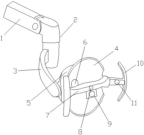
[0013] Such as figure 1 As shown, a dental light includes a mounting rod 1, a connecting rod 2, an arc plate 3 and a reflective disc 4, the connecting rod 2 is arranged at the lower end of the mounting rod 1, and the connecting rod 2 is hinged to the mounting rod 1, so The arc-shaped plate 3 is arranged on one side of the connecting rod 2, one end of the arc-shaped plate 3 is fixedly connected with the connecting rod 2, and the bottom of the reflective disk 4 is equipped with a cooling block 5 and a main light source 6, and the arc-shaped plate 3 is connected with the connecting rod 2 The heat dissipation block 5 is fixedly connected, the middle part of the reflective disk 4 is provided with a crossbar 7, the middle part of the crossbar 7 is provided with a light-transmitting hole 8, the bottom of the crossbar 7 is equipped with a camera 9, and the two ends of the crossbar 7 are arranged There is a handle 10, the handle 10 is arranged in a T shape, and a side light source 11 i...


PUM


Abstract

The invention discloses an oral cavity lamp comprising an installation rod, a connection rod, an arc-shaped plate and a reflection disc. The connection rod is arranged on the lower end of the installation rod; the connection rod is hinged with the installation rod; the arc-shaped plate is mounted on one side of the connection rod; one end of the arc-shaped plate is fixedly connected with the connection rod; the reflection disc bottom is provided with a heat radiating block and a main light source; the arc-shaped plate is fixedly connected with the heat radiating block; a transverse rod is mounted on the middle part of the reflection disc; a light hole is formed in the middle of the transverse rod; a camera is mounted on the bottom of the transverse rod; two ends of the transverse rod are provided with handles; each handle is T-shaped; and a lateral light source is disposed in each handle. The oral cavity lamp can be conveniently installed and easy to adjust, and can meet various observation demands.

Description

technical field [0001] The invention relates to a dental light. Background technique [0002] The mouth is the beginning of the digestive tract. The front fissure communicates with the outside world, and the back passes through the pharynx to continue with the pharynx. There are teeth, tongue and other organs in the oral cavity. The front wall of the oral cavity is the lips, the side wall is the cheeks, the roof is the palate, and the floor of the mouth is the mucosa and muscles. The oral cavity is divided into the anterolateral oral vestibule and the posteromedial oral cavity by the upper and lower dental arches; when the upper and lower teeth occlude, the oral vestibule and the oral cavity proper can be communicated through the gap behind the third molars. Clinically, when the patient's teeth are tightly closed, the mouth gag or cannula can be placed through this channel to inject drugs or nutrients while preventing tongue biting. The lips form the front wall of the or...

Claims


Application Information

Patent Timeline
Patent Type & Authority Applications(China)
IPC IPC(8): A61B1/24A61B1/06
CPCA61B1/0684A61B1/24
Inventor 龚素华
Owner CHENGDU XUNDE SCI & TECH
Why Eureka
Try Eureka