Device for measuring contact force of foot of human body

A measuring device and contact force technology, applied in the directions of diagnostic recording/measurement, medical science, diagnosis, etc., can solve the problems that the pressure sensor cannot contact the force information effectively, and the force measuring insole is expensive, so as to ensure the wearing comfort and reduce the cost. Small loss, high reliability effect

Active Publication Date: 2017-03-08
HARBIN INST OF TECH
View PDF6 Cites 4 Cited by
  • Summary
  • Abstract
  • Description
  • Claims
  • Application Information

AI Technical Summary

Problems solved by technology

[0004] The present invention solves the problem that the existing force-measuring platform and force-measuring insole are expensive, and the pressure sensor cannot effectively measure the contact force information of different motion states, and further provides a human foot contact force measuring device

Method used


Image

  • Device for measuring contact force of foot of human body
  • Device for measuring contact force of foot of human body
  • Device for measuring contact force of foot of human body

Examples


specific Embodiment approach 1

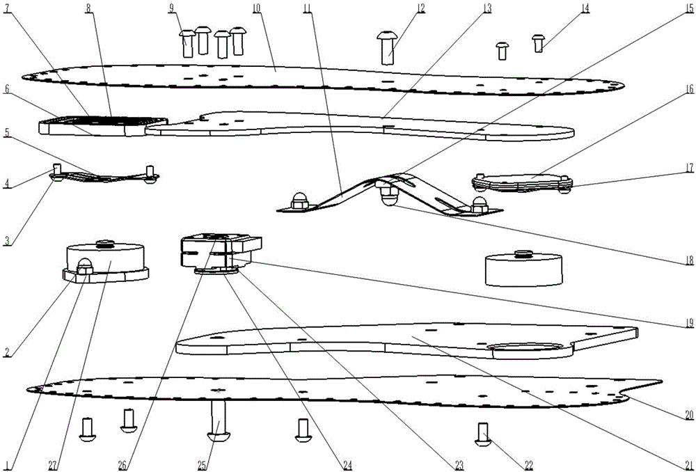
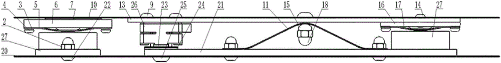
[0024] Specific implementation mode one: as Figure 1~4 As shown, the human foot end contact force measuring device of this embodiment includes a CM base 1, a front CM card slot 5, a needle row groove 6, a needle row 7, a roller row gasket 8, a top steel plate 10, and a tension spring Sheet 11, top carbon plate 13, CM cover plate 16, rear CM card slot 17, three-dimensional force sensor 19, bottom steel plate 20, bottom carbon plate 21 and two one-dimensional force sensors 27; bottom carbon plate 21 is fixed on the bottom steel plate 20, the top carbon plate 13 is fixed on the lower end surface of the top steel plate 10, a three-dimensional force sensor 19 and two one-dimensional force sensors 27 are arranged between the bottom steel plate 20 and the top steel plate 10, and the three-dimensional force sensor 19 is located at Below the sole of the forefoot, one of the two one-dimensional force sensors 27 is fixed on the upper end surface of the bottom steel plate 20 through the ...

specific Embodiment approach 2

[0029] Specific implementation mode two: as Figure 1~2 As shown, one of the two one-dimensional force sensors 27 in this embodiment is fixed on the bottom steel plate 20 through the M4 semi-cylindrical hexagon head cap nut 2 and the M4×8 hexagon socket head cap screw 22 . Such a design makes the one-dimensional force sensor stronger when subjected to impact loads. Other components and connections are the same as those in the first embodiment.

specific Embodiment approach 3

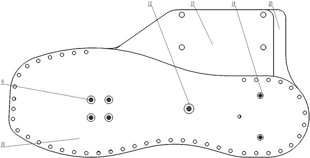
[0030] Specific implementation mode three: as figure 1 , figure 2 with image 3 As shown, the tension reed 11 of this embodiment is fixedly connected to the upper and lower steel plate structures through M5×12 hexagon socket head cap screws 12, semicircular nuts 15 and M5 semicylindrical hexagon head cap nuts 18. Such a design can prevent the upper steel plate from collapsing. Other compositions and connections are the same as those in Embodiment 1 or 2.


PUM


Abstract

The invention relates to a measuring device, particularly to a device for measuring a contact force of a foot of a human body. With the measuring device, problems that costs for manufacturing the existing force-measuring platform and force-measuring shoes are high and the pressure sensor can not measure contact force information effectively in different motion states can be solved. A three-dimensional force sensor and two one-dimensional force sensors are arranged between a bottom steel plate and a top steel plate; a roller pin row structure is arranged right above one of the two one-dimensional force sensors and below the top steel plate; and a roller row gasket is arranged between the roller pin row and the top steel plate. The other one of the two one-dimensional force sensors is arranged below calcaneus, is installed in a circular groove of a bottom carbon plate and is fixedly connected with the bottom steel plate. A rear CM clamp groove is fixedly installed on a lower end surface of the top steel plate by a CM cover plate and is arranged right above one of the two one-dimensional force sensors. A tightening reed is arranged below a foot arch. The device provided by the invention is used for measuring the contact force of the foot of the human body.

Description

technical field [0001] The invention relates to a human body foot force measurement device, in particular to a measurement device capable of accurately measuring the plantar support reaction force of a human body under various motion states. Background technique [0002] Plantar pressure analysis is an important way to obtain information about human body movement. Currently, the most advanced method for measuring plantar pressure load distribution is to use a dedicated force-measuring platform and force-measuring insole, but these force-measuring systems are very expensive. In addition, pressure sensors can also be placed on the bottom of the sensing boots to measure the ground reaction force of the toe, heel, and exoskeleton robot load and self-weight. Since the center of the sole bearing pressure is constantly changing with movement, Therefore, it is difficult to ensure the effective measurement of contact force information under different motion states, and it is impossib...

Claims


Application Information

Patent Timeline
Patent Type & Authority Applications(China)
IPC IPC(8): A61B5/103
CPCA61B5/1038
Inventor 李满天邓静王鹏飞郭伟夏宇盛文涛查富生
Owner HARBIN INST OF TECH
Why Eureka
Try Eureka