Stamping lower die with adjustable angle

An adjustable and mold technology, applied in the field of stamping processing, can solve the problems of loose mold seat and support block, affecting mold processing accuracy, time-consuming and laborious, etc., to achieve the effect of intuitive adjustment, intuitive and accurate angle, and simple operation.

Inactive Publication Date: 2017-03-08
李远强
View PDF1 Cites 2 Cited by
  • Summary
  • Abstract
  • Description
  • Claims
  • Application Information

AI Technical Summary

Problems solved by technology

[0003] Although the above solution solves the problem that the bending angle can be adjusted by the processing company, but every time it is used, it is necessary to manually replace the support block and adjust the distance between the two mold seats. Looseness occurs between the seat and the support block, which affects the machining accuracy of the mold

Method used


Image

  • Stamping lower die with adjustable angle
  • Stamping lower die with adjustable angle
  • Stamping lower die with adjustable angle

Examples


Embodiment 1

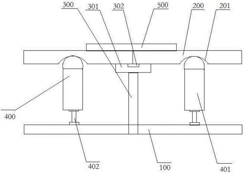
[0024] Such as figure 1 As shown, a stamping lower mold with adjustable angle includes a base 100 arranged horizontally, a central support device 300, two lower molds 200 and a lifting device 400 that are mutually symmetrical and rotatably connected to each other;

[0025] The lower part of the lower mold 200 is provided with symmetrically distributed arc-shaped slots 201;

[0026] The lifting device 200 is arranged between the base 100 and the lower mold 200, and the number of the lifting device 200 is an even number, and the lifting device 400 is symmetrically distributed; the lifting device 400 includes a supporting part 401 and a lifting rod 402 connected in sequence, the lifting rod 402 is an electric control lifting rod; the top of the support part 401 is in the shape of a semi-cylindrical, and its cross-section is semicircular, and its arc is larger than the arc-shaped slot 201, so as to ensure that the support part 401 and the lower mold 200 are connected in a circular...

Embodiment 2

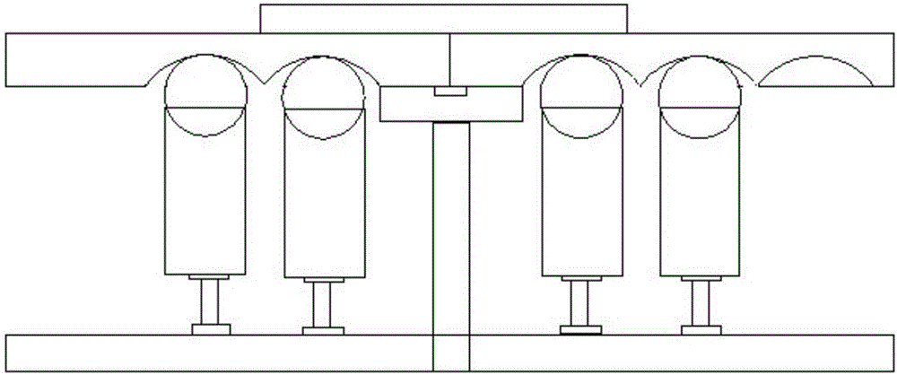
[0031] Such as image 3 As shown, a stamping lower mold with an adjustable angle includes a base 100 arranged horizontally, a central support device 300, two lower molds 200 and a lifting device 400 that are mutually symmetrical and rotatably connected to each other; the bottom of the lower mold 200 The arc-shaped slot 201 is provided with symmetrical distribution; the lifting device 200 is arranged between the base 100 and the lower mold 200, and the number of the lifting device 200 is an even number, and the lifting device 400 is symmetrically distributed; the lifting device 400 includes The supporting part 401 and the elevating rod 402 connected in sequence, the elevating rod 402 is an electric control elevating rod; the top of the supporting part 401 is in the shape of a semi-cylindrical, its cross-section is semicircular, and its radian is larger than that of the arc-shaped slot 201, ensuring the support Part 401 and the lower part of the lower mold 200 are connected in c...


PUM


Abstract

The invention provides a stamping lower die with an adjustable angle and relates to the field of stamping equipment. The stamping lower die comprises a base horizontally arranged and further comprises a central support device, two lower dies which are symmetrical with each other and are in rotating connection with each other, and lifting devices, wherein arc-shaped clamping grooves are symmetrically distributed in the lower sides of the lower dies; the lifting devices are arranged between the base and the lower dies, the lifting devices comprise support parts and lifting rods which are sequentially connected, and the lifting rods are electrically controlled lifting rods; the tops of the support parts are semi-cylindrical, the cross sections of the support parts are semi-circular, the radian of the support parts is larger than that of the arc-shaped clamping grooves, and arc rotating type connection between the support parts and the lower sides of the lower dies is ensured; and the central support device is arranged below the rotating connection part of the two lower dies, the bottom of the central support device is fixed to the base, and a protection plate is further arranged between the central support device and the two lower dies. The problem that the bending degree of the traditional die cannot be adjusted is solved.

Description

technical field [0001] The invention relates to the field of stamping processing, in particular to a lower stamping mold with an adjustable angle. Background technique [0002] In stamping technology, the stamping die is usually divided into an upper die and a lower die. The lower die cannot be adjusted, and the bending angle of the corresponding workpiece cannot be adjusted, which limits the scope of production and processing. When the specifications of the workpiece to be stamped change, the die often needs to be adjusted. It is troublesome to replace the whole set, the cost is also high, and the efficiency is low, which is not conducive to mass production. In the prior art, a utility model patent with the patent number CN201521067632.6 discloses a solution: a stamping lower die, including a base and two lower dies; the base is arranged horizontally; the two lower dies The molds are symmetrically distributed and slidably connected with the base; the lower mold includes a ...

Claims


Application Information

Patent Timeline
Patent Type & Authority Applications(China)
IPC IPC(8): B21D37/10B21D37/12B21D55/00
CPCB21D37/10B21D37/12B21D55/00
Inventor 李远强
Owner 李远强
Why Eureka
Try Eureka