Rolling mechanism of drive shaft of woodworking machine

A technology for a drive shaft and a woodworking machine, which is applied to wood processing appliances, manufacturing tools, circular saws, etc., can solve the problems of complexity, many accessories, and inconvenience, and achieve the effects of small oscillation amplitude, extended service life and low cost.

Inactive Publication Date: 2018-11-30
KUANG YUNG MACHINERY
View PDF4 Cites 0 Cited by
  • Summary
  • Abstract
  • Description
  • Claims
  • Application Information

AI Technical Summary

Problems solved by technology

[0004] The assembly and disassembly of the bearing 21 of the transmission shaft 10 of the traditional woodworking machine, such as the above-mentioned accessories are many and complicated, the assembly and disassembly is time-consuming and labor-intensive, and it is very inconvenient. Loss, the transmission shaft 10 will produce oscillation amplitude, which will affect the quality of cut wood

Method used


Image

  • Rolling mechanism of drive shaft of woodworking machine
  • Rolling mechanism of drive shaft of woodworking machine
  • Rolling mechanism of drive shaft of woodworking machine

Examples


Embodiment Construction

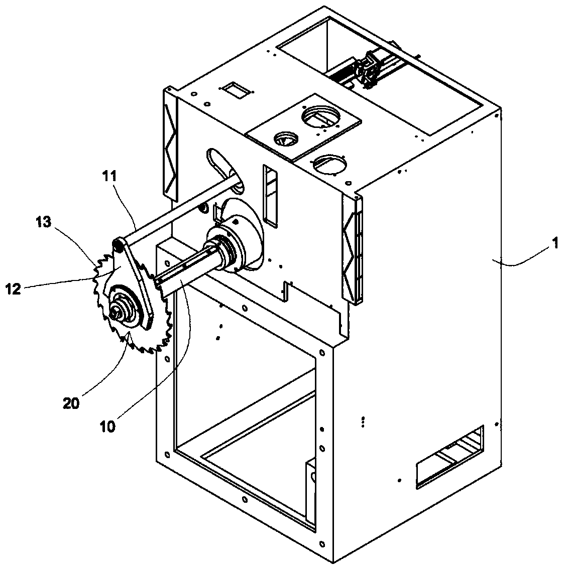
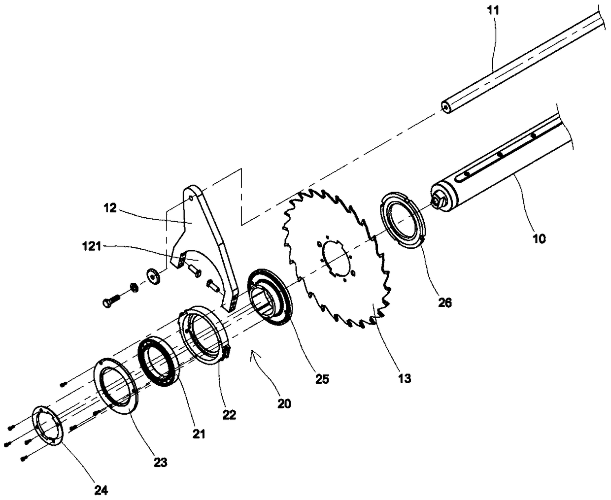
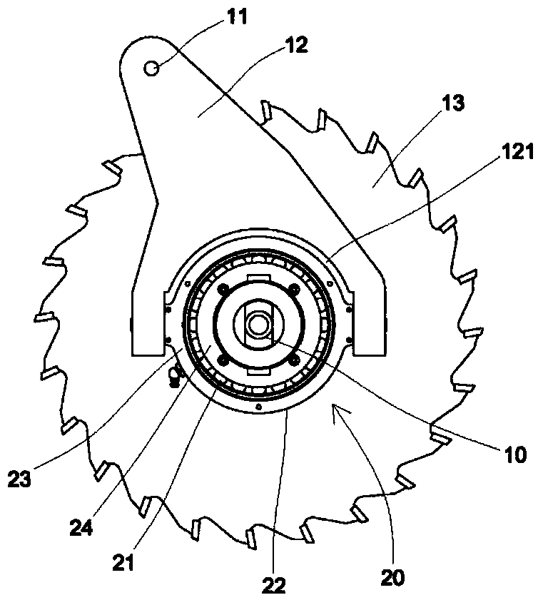
[0038] The present invention is a rolling mechanism of a drive shaft of a woodworking machine, such as Figure 5-8 As shown, a power mechanism (generally a motor, not shown) is assembled in a box body 30, and the power mechanism provides a transmission shaft 400 rotational force, and the transmission shaft 400 protrudes outside the box body 30, and the box body 30 is internally pivoted. Connect a stabilizing bar 31, and the stabilizing bar 31 also protrudes outside the casing 30. The stabilizing bar 31 locates a stabilizing plate 32. The stabilizing plate 32 is slightly triangular. A rolling mechanism 40 is connected, and the rolling mechanism 40 is connected to at least one saw blade 43 and a transmission shaft 400. The rolling mechanism 40 includes:

[0039] Two plates 41, the plates 41 are pivotally connected to the two ends of the tiger's mouth 321, the plate 41 is a circular piece, the two ends of the tiger's mouth 321 are pivotally connected with the rivets 411 as the pl...


PUM


Abstract

The invention provides a rolling mechanism of a wood working machine transmission shaft. A power mechanism is used for providing rotating force of the transmission shaft and assembled in a box. The box is connected with a stabilization bar in a pivoted manner, and the stabilization bar positions a stabilization plate. A thumb-index web is arranged on the stabilization plate, and a rolling mechanism body is connected to each of the two ends of the thumb-index web in a pivotal manner. At least one saw web and the transmission shaft are connected to the rolling mechanism bodies. The rolling mechanism is characterized in that the rolling mechanism body is connected to each of the two ends of the thumb-index web in the pivotal manner and comprises two sheet bars and a positioning ring, wherein the sheet bars are connected to the two ends of the thumb-index web in a pivotal manner, the positioning ring is combined to the transmission shaft and rotates along with the transmission shaft, at least one concave ring is arranged on the periphery of the positioning ring, the peripheral edges of the sheet bars enter and are clamped in the concave ring, and the transmission shaft is positioned in an inner ring of the positioning ring; and the positioning ring of the transmission shaft can smoothly rotate and be stably supported through the sheet bars of the stabilization plate, the sheet bars are arranged at the outer portion of the positioning ring, and assembling and disassembling are easy.

Description

【Technical field】 [0001] The invention relates to a rolling mechanism of a drive shaft of a woodworking machine, especially refers to a pivoting ring stably clamped by peripheral plates, so that the drive shaft rotates synchronously, without internal bearings, and is completely assembled and disassembled from the outside, which is faster Convenient, when the transmission shaft rotates rapidly, it is a rolling mechanism for the transmission shaft of a woodworking machine that reduces vibration and improves the quality of sawn wood. 【Background technique】 [0002] Bearings are mechanically used to support rotating bodies or linear reciprocating bodies. When other parts move relative to each other on the shaft, they are used to maintain the center position of the shaft and control the movement. The bearings can slide with the shaft. , to minimize the friction generated when the shaft rotates, so that the shaft can exert its maximum efficiency; the bearing needs regular maintena...

Claims


Application Information

Patent Timeline
Patent Type & Authority Patents(China)
IPC IPC(8): B27B5/02B27B5/29
Inventor 张志州
Owner KUANG YUNG MACHINERY
Why Eureka
Try Eureka