
Flow regulating valve, heat pump system and control method thereof

A technology of flow regulating valve and heat pump system, which is applied to lift valves, refrigerators, valve devices, etc., can solve problems such as inconvenience of use, and achieve the effects of improving user comfort, improving defrosting effect and convenient use.

Active Publication Date: 2018-12-07
GREE ELECTRIC APPLIANCES INC
View PDF6 Cites 0 Cited by
  • Summary
  • Abstract
  • Description
  • Claims
  • Application Information

AI Technical Summary

Problems solved by technology

[0002] Existing flow regulating valves generally have only one spool, and the adjustment of the flow is realized by changing the positional relationship between the spool and the valve port. The minimum flow, maximum flow and flow adjustment accuracy are fixed. When the flow requirements change It is necessary to replace the flow regulating valve, which is inconvenient to use

Method used


Image

  • Flow regulating valve, heat pump system and control method thereof
  • Flow regulating valve, heat pump system and control method thereof
  • Flow regulating valve, heat pump system and control method thereof

Examples


Embodiment Construction

[0027] The present invention is described below based on examples, but the present invention is not limited to these examples. In the following detailed description of the present invention, some specific details are described in detail. Those skilled in the art can fully understand the present invention without the description of these details. In order to avoid obscuring the essence of the present invention, well-known methods, processes, procedures, and components are not described in detail.

[0028] In addition, those of ordinary skill in the art should understand that the drawings provided herein are for illustrative purposes, and the drawings are not necessarily drawn to scale.

[0029] Unless the context clearly requires, the words "including", "including" and other similar words in the entire specification and claims should be interpreted as inclusive rather than exclusive or exhaustive meanings; in other words, "including but not limited to" Meaning.

[0030] In the desc...


PUM


Abstract

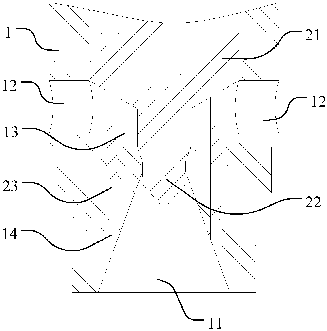
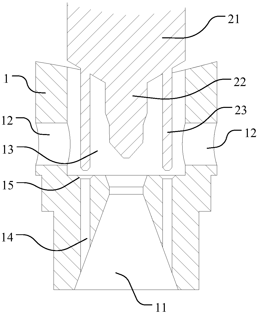
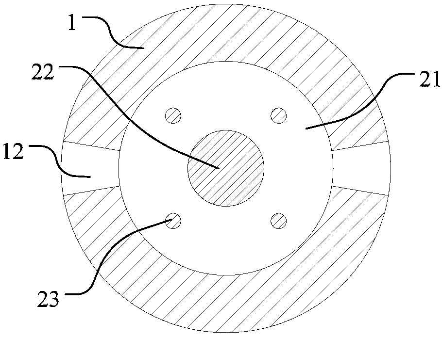
The invention discloses a flow regulating valve, a heat pump system and a control method. The flow regulating valve includes a valve seat, the valve seat is provided with a first port and a second port, and a main channel and a bypass channel communicating with the first port and the second port are provided in the valve seat, so A first spool for opening and closing the main flow path and a second spool for opening and closing the bypass flow path are also arranged in the valve seat, the first spool and the second valve Core linkage. The flow regulating valve provided by the present invention has a main flow path and a bypass flow path. By changing the positions of the first spool and the second spool, the flow conditions in the main flow path and the bypass flow path can be changed to meet different flow requirements. It is convenient to use. In addition, since the first valve core and the second valve core are in a linkage relationship, only one valve core is needed to drive the two valve cores to realize the linkage of the two valve cores, and the structure is simple.

Description

Technical field [0001] The invention relates to the field of flow regulation, and more specifically to a flow regulation valve, a heat pump system and a control method thereof. Background technique [0002] Existing flow control valves generally have a spool, and the flow is adjusted by changing the positional relationship between the spool and the valve port. The minimum flow, maximum flow and flow adjustment accuracy are all fixed. When the flow requirements change When the flow control valve needs to be replaced, it is inconvenient to use. Summary of the invention [0003] In view of this, one of the objectives of the present invention is to provide a flow regulating valve that can meet different flow requirements, is easy to use, has a good defrosting effect, and a heat pump system and its control method. [0004] In the first aspect, a flow regulating valve is provided. [0005] A flow regulating valve includes a valve seat, a first port and a second port are provided on the va...

Claims


Application Information

Patent Timeline
Patent Type & Authority Patents(China)
IPC IPC(8): F16K1/00F16K1/52F25B41/06F25B49/02F25B41/34
CPCF16K1/00F16K1/52F25B49/02F25B2341/06F25B2600/2513F25B41/31
Inventor 赖路璇王春罗永宏肖新奎梁章平
Owner GREE ELECTRIC APPLIANCES INC
Learn More