

Magneto-rheological valve structure with a combined three-dimensional helical flow channel
Patent Information
- Authority / Receiving Office
- CN · China
- Patent Type
- Patents(China)
- Current Assignee / Owner
- HEILONGJIANG UNIVERSITY OF SCIENCE AND TECHNOLOGY
- Publication Date
- 2015-11-18
- Estimated Expiration
- Not applicable · inactive patent
Smart Images
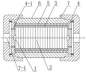
Figure 1 
Figure 2 
Figure 3
Abstract
Description
Technical field
[0001] The invention relates to a hydraulic control valve, in particular to the improvement of a magneto-rheological valve liquid flow channel, in particular to a magneto-rheological valve structure of a three-dimensional spiral liquid flow channel. Background technique
[0002] Compared with traditional hydraulic control valves, magnetorheological valves control the flow of magnetorheological fluid through the valve by controlling the magnitude of the excitation coil current, without moving mechanical parts. Compared with traditional mechanical valves, magnetorheological fluid control valves Simple structure, small size, easy to control, fast response, low working noise, wear resistance, high reliability and low cost. The hydraulic control range of magneto-rheological valves has its own limitations. One is that the flow direction of the magnetorheological fluid in the magnetic gap space must be perpendicular to the direction of the magnetic field; the secon...