Coaxial rectangle ring-based dual-polarized chipless RFID tag antenna

A technology of RFID tags and rectangular rings, applied in the direction of loop antennas, antennas, antenna parts, etc., can solve the problems of unfavorable antenna miniaturization and increase in antenna size, and achieve size reduction, coding capacity improvement, and increased coding capacity Effect

Pending Publication Date: 2017-03-08
SOUTH CHINA UNIV OF TECH
View PDF1 Cites 10 Cited by
  • Summary
  • Abstract
  • Description
  • Claims
  • Application Information

AI Technical Summary

Problems solved by technology

However, most tag antennas based on frequency domain coding will add a resonator for each additional bit of coding, t

Method used


Image

  • Coaxial rectangle ring-based dual-polarized chipless RFID tag antenna
  • Coaxial rectangle ring-based dual-polarized chipless RFID tag antenna
  • Coaxial rectangle ring-based dual-polarized chipless RFID tag antenna

Examples


Example Embodiment

[0028] Example

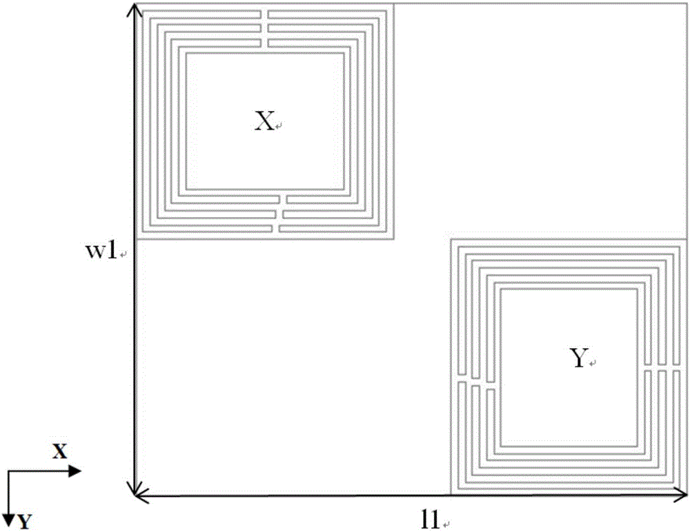
[0029] This embodiment discloses a dual-polarized chipless RFID tag antenna based on a coaxial rectangular ring, used for a chipless tag antenna in a radio frequency identification system, and includes a dielectric substrate, an X-polarized resonator and a Y-polarized resonator. The X-polarized resonator and Y-polarized resonator are printed on the same surface of the dielectric substrate.

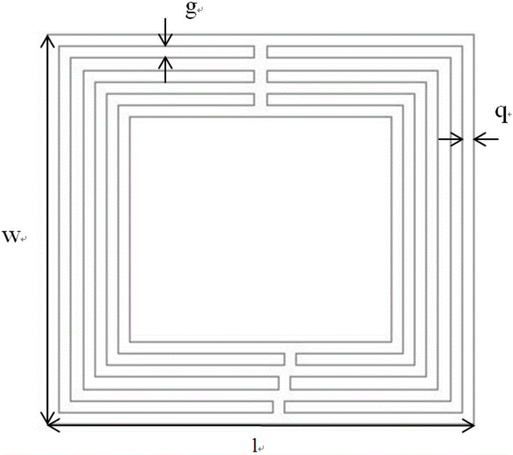
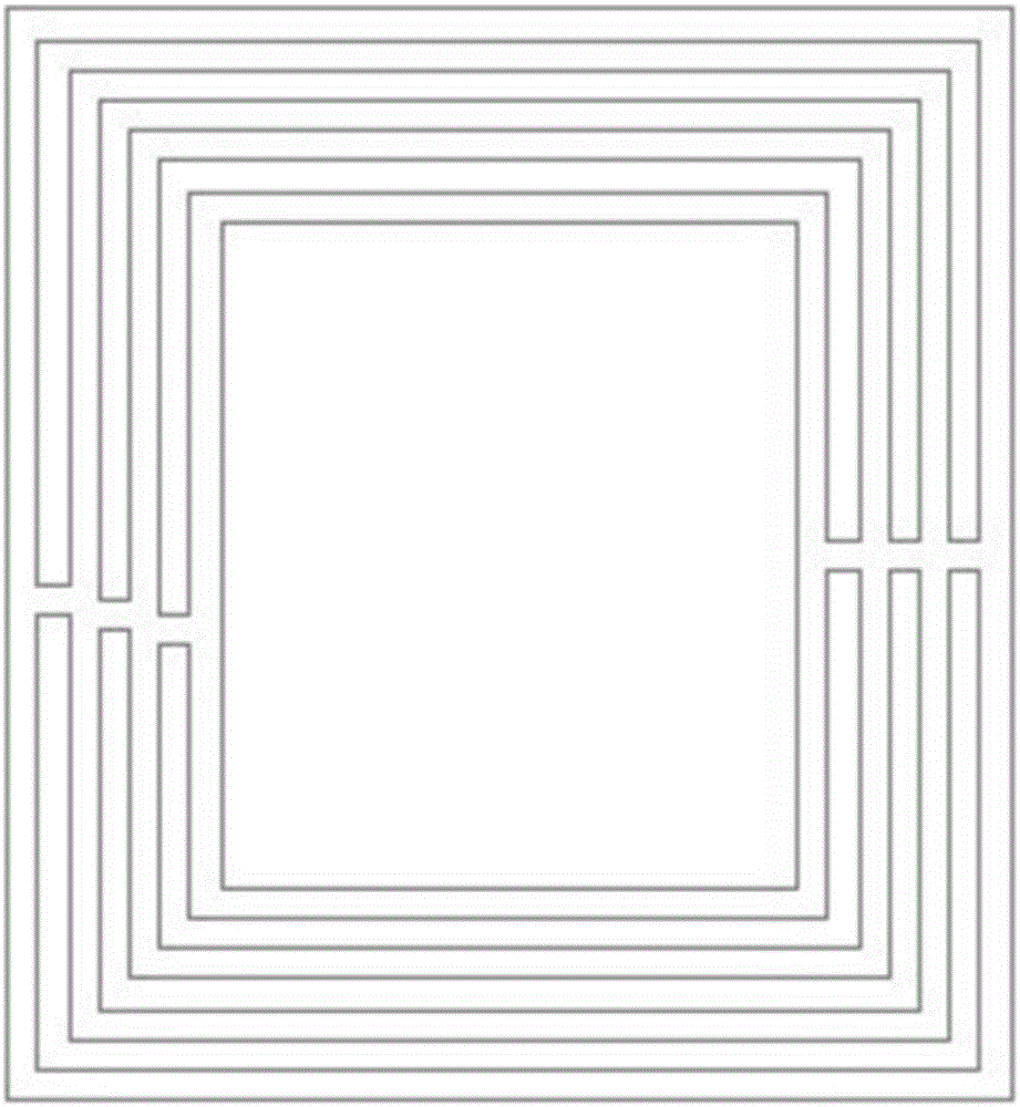
[0030] The X-polarized resonator is formed by four coaxial rectangular rings, and every two adjacent rectangular rings are connected by two upper and lower short wires respectively connecting the upper and lower sides together. The length and width of the short wire are both 0.2mm.

[0031] The Y-polarized resonator is obtained by rotating the X-polarized resonator 90 degrees in a clockwise direction.

[0032] The dielectric substrate material adopts Teflon (Teflon, tm), the dielectric constant is 2.55, the loss tangent is 0.0014, and the thickness is 0.5 mm.

[0033] The working ...


PUM

PropertyMeasurementUnit
Thicknessaaaaaaaaaa

Abstract

The invention discloses a coaxial rectangle ring-based dual-polarized chipless RFID tag antenna, which is used for encoding an article in a chipless tag system and comprises a dielectric substrate, an X polarization resonator and a Y polarization resonator, wherein the X polarization resonator comprises four coaxial rectangle rings; the Y polarization resonator is obtained by rotating the X polarization resonator at 90 degrees along the clockwise direction; and the X polarization resonator and the Y polarization resonator are printed on the dielectric substrate and are distributed on the same horizontal plane in a diagonal line. The RFID tag antenna disclosed by the invention is a magnetic antenna and is insensitive to different adhered dielectric substrates. Meanwhile, the RFID tag antenna disclosed by the invention is the dual-polarized antenna; the antenna can be repeatedly used for encoding within a same frequency range; and the encoding capacity of the antenna is improved.

Description

technical field [0001] The invention relates to the field of chipless tag antennas, in particular to a dual-polarized chipless RFID tag antenna based on a coaxial rectangular ring. Background technique [0002] According to the different working mechanisms and methods of chipless tag antennas, chipless tag encoding methods can be roughly divided into encoding technologies based on time domain, frequency domain and phase. The coding technology based on the time domain refers to encoding by receiving transmission signals at different delay times in the time domain. Since the signal attenuates with the transmission, the number of coding bits in the time domain coding is very small; phase coding Technology refers to encoding by measuring the different phases of the transmission signal, and the number of encoding bits based on this method is also very limited; frequency domain encoding technology refers to encoding in the frequency domain by whether a series of resonators generat...

Claims


Application Information

Patent Timeline
IPC IPC(8): H01Q1/22H01Q7/00H01Q15/24
CPCH01Q1/2225H01Q7/00H01Q15/24
Inventor 黄惠芬苏丽
Owner SOUTH CHINA UNIV OF TECH
Why Eureka
Try Eureka