Uplink and downlink interference coordination processing method and apparatus
A processing method and processing device technology, applied in the field of communication, capable of solving problems such as interference coordination
- Summary
- Abstract
- Description
- Claims
- Application Information
AI Technical Summary
Problems solved by technology
Method used
Image
Examples
Embodiment 1
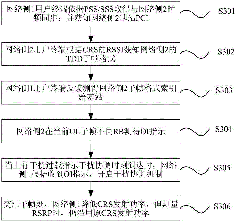
[0209] image 3 It is a schematic flow chart of downlink-to-uplink interference coordination according to preferred embodiment 1 of the present invention, such as image 3 shown, including:
[0210]Step S301, the user terminal on the network side 1 obtains frequency and symbol synchronization with the base station on the adjacent frequency network side 2 according to PSS (Primary Synchronization Signal, Primary Synchronization Signal) and / or SSS (Secondary Synchronization Signal, Secondary Synchronization Signal).
[0211] The specific process is: the user terminal obtains frequency and symbol synchronization with the base station on the adjacent network side 2 according to the PSS and / or SSS, and learns the PCI (Physical-layer Cell Identity, Physical-layer Cell Identity) of the base station on the network side 2 community ID).
[0212] Step S302 , the user terminal on the network side 1 obtains the TDD subframe format of the network side 2 according to the RSSI power value....
Embodiment 2
[0223] Figure 5 It is a schematic flow chart of downlink-to-uplink interference coordination according to preferred embodiment 2 of the present invention, such as Figure 5 As shown, steps S501 to S506 are included. Compared with the preferred embodiment 1, steps S502 and S506 are different from steps S302 and S306. The difference is that in step S502, the user terminal on the network side 1 obtains the TDD subframe of the same-frequency network side 2 base station according to the decoded network side 2 PBCH type.
[0224] The specific process is: the user terminal on the network side 1 decodes the PBCH of the network side 2, and obtains the TDD uplink and downlink configuration format of the base station carried by the network side information SIB1 (System Information Blocks). Wherein, the transmission period of SIB1 is 80ms, and in order to ensure the correct reception of the cell edge users, the same transmission will be repeated 3 times in one transmission period.
[...
Embodiment 3
[0227] Image 6 is a schematic flow chart of downlink-to-uplink interference coordination according to preferred embodiment 3 of the present invention, as shown in Image 6 As shown, steps S601 to S606 are included. Compared with the preferred embodiment, steps S601-S605 are the same as steps S301-S305, the difference is that in step S606, at the intersection subframe, that is, the network side 1 is a DL subframe, and the network side 2 is a UL subframe; Side 1 lowers the CRS transmit power for downlink transmission, which will reduce the UL transmission interference to network side 2, but for user terminals in network side 1, when the CRS transmit power is reduced, RSRP measurement is not performed, that is, the cell selection process is not performed. In this way, the problem of cell shrinkage caused when the user terminal in the local cell selects the serving cell to access according to the reduced RSRP is avoided.
PUM
 Abstract
Description
Claims
Application Information
 - R&D
- Intellectual Property
- Life Sciences
- Materials
- Tech Scout
- Unparalleled Data Quality
- Higher Quality Content
- 60% Fewer Hallucinations
Browse by: Latest US Patents, China's latest patents, Technical Efficacy Thesaurus, Application Domain, Technology Topic, Popular Technical Reports.
© 2025 PatSnap. All rights reserved.Legal|Privacy policy|Modern Slavery Act Transparency Statement|Sitemap|About US| Contact US: help@patsnap.com


