Interference coordination method in 5G communication room subsystem based on Xn interface
A communication room and sub-system technology, applied in the field of communication, can solve the problems of network performance degradation, poor user service experience, unsatisfactory interference coordination effect, etc., to achieve the effect of interference coordination and good resource allocation
- Summary
- Abstract
- Description
- Claims
- Application Information
AI Technical Summary
Problems solved by technology
Method used
Image
Examples
Embodiment 1
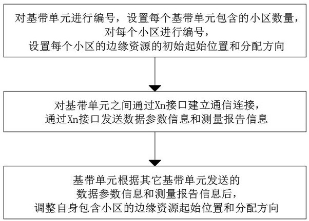
[0045] like figure 1 As shown, a 5G communication room sub-system coordination interference method based on Xn interface, the specific process is as follows:
[0046] Number the baseband unit BBU, the numbers of the baseband unit BBU are BBU1, BBU2, ..., set the number of cells included in each baseband unit, number each cell, and each cell is numbered Cell1, Cell2, ..., there are two cases for the number of cells contained in each baseband unit BBU, namely, each baseband unit BBU contains two cell specifications and each baseband unit BBU contains four cell specifications, and the edge resources of each cell are set. Initial starting position and distribution direction.
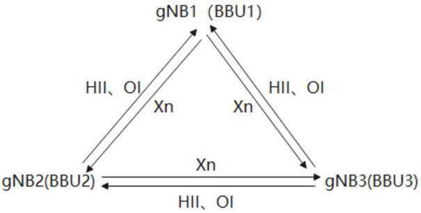
[0047] A communication connection is established between the baseband units BBU through the Xn interface, and data parameter information and measurement report information MR are sent through the Xn interface. The data parameter information includes high interference indication HII, overload indication OI, ...
Embodiment 2
[0068]Dual baseband unit BBU, a single baseband unit BBU is a two-cell specification, the maximum interference adjacent cell is less than or equal to two cells with a bandwidth of 100MHz, a total of 273RB, and the numbers from low frequency to high frequency are 0~272. The baseband unit BBU1 exchanges information through the Xn interface to obtain the baseband The number of cells in the unit BBU2, and obtain the edge starting position and allocation direction of each cell in the baseband unit BBU1, determine the number of possible neighboring cells, and adjust the edge resource selection of each cell within its own coverage.
[0069] like figure 2 shown:
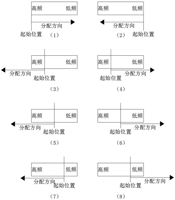
[0070] Case 1: Cells in baseband unit BBU1: Cell1 and Cell2, cells in baseband unit BBU2: Cell3 and Cell4, baseband unit BBU1 Cell1 PCI167 has only one neighbor Cell3 PCI100; Cell1 uses edge cell resource allocation (1), the starting position of edge resources It is RB272, and the allocation direction is from RB272 to RB0;...
Embodiment 3
[0073] Dual baseband unit BBUs, single baseband unit BBUs are all 4 cells, the maximum interference adjacent cell is less than or equal to 4 cells with a bandwidth of 100MHz, a total of 273RB, and the numbers from low frequency to high frequency are 0~272. BBU1 exchanges information through the Xn interface to obtain cells in BBU2 and obtain the edge starting position and allocation direction of each cell in BBU1, determine the number of possible neighbor cells, and adjust the edge resource selection of each cell within its own coverage.
[0074] Assume that the number of interfering cells is 4: the cells in the baseband unit BBU1: Cell1, Cell2, Cell3, and Cell4, and the cells in the baseband unit BBU2: Cell5, Cell6, Cell7, and Cell8.
[0075] Adjacent cell interference of baseband unit BBU1 Cell1: Cell5, Cell6, Cell7 and Cell8; Adjacent cell interference of baseband unit BBU1Cell2: Cell6, Cell7 and Cell8; Adjacent cell interference of baseband unit BBU1 Cell3: Cell7 and Cell8;...
PUM
 Abstract
Description
Claims
Application Information
 - R&D
- Intellectual Property
- Life Sciences
- Materials
- Tech Scout
- Unparalleled Data Quality
- Higher Quality Content
- 60% Fewer Hallucinations
Browse by: Latest US Patents, China's latest patents, Technical Efficacy Thesaurus, Application Domain, Technology Topic, Popular Technical Reports.
© 2025 PatSnap. All rights reserved.Legal|Privacy policy|Modern Slavery Act Transparency Statement|Sitemap|About US| Contact US: help@patsnap.com


