
FEC decoding system with optical line crossing function realized based on electric domain and method

An optical line crossover and functional technology, applied in the field of solving FEC systems, can solve the problems of increasing capital investment in solving FEC equipment, increasing the failure rate of the overall equipment and maintenance time, etc.

Inactive Publication Date: 2017-03-08
TOEC TECH
View PDF0 Cites 2 Cited by
  • Summary
  • Abstract
  • Description
  • Claims
  • Application Information

AI Technical Summary

Problems solved by technology

Adding de-FEC equipment will not only increase capital investment, but also increase the failure rate and maintenance time of the overall equipment

Method used


Image

  • FEC decoding system with optical line crossing function realized based on electric domain and method
  • FEC decoding system with optical line crossing function realized based on electric domain and method
  • FEC decoding system with optical line crossing function realized based on electric domain and method

Examples


Embodiment Construction

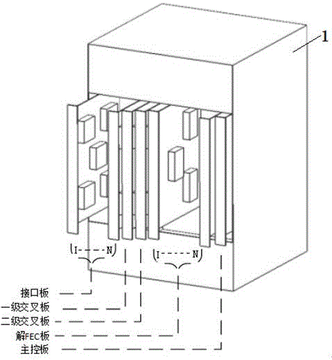
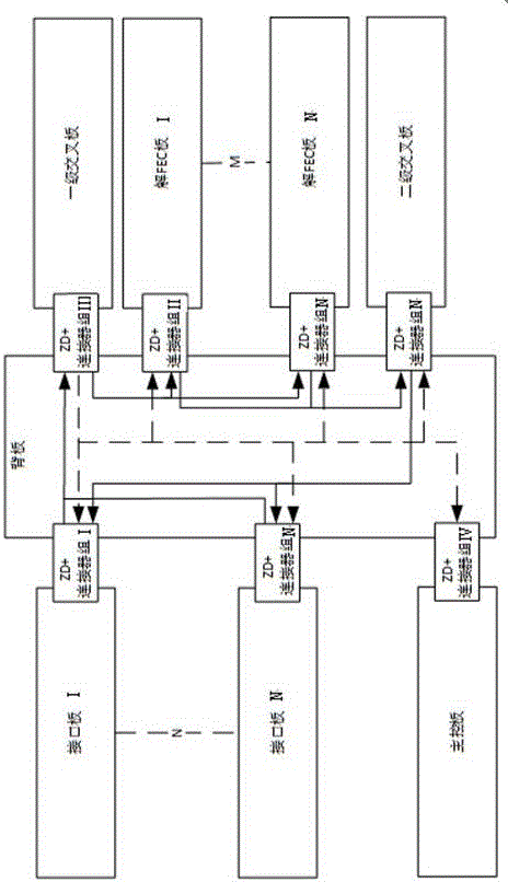
[0030] Such as figure 1 , figure 2 As shown, a de-FEC system with optical line crossover function based on an electrical domain implementation includes a housing 1, a backplane, an interface board, a de-FEC board, a first-level cross board, a second-level cross board, and a main control board.

[0031] Several ZD+ connectors are fixed on the backplane, and the backplane is fixed in the housing 1. Several interface boards are respectively connected to the first and second crossover boards through the ZD+ connector by the data bus. The level crossover board is connected to several FEC solutions through the ZD+ connector through the data bus, and the control bus for the main control board is connected to the first level crossover board, the second level crossover board, several interface boards, and several solution FEC through the ZD+ connector. Board connection.

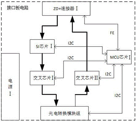
[0032] Such as image 3 As shown, the circuit of the interface board includes SI chip I, cross chip I, cross chip II, M...


PUM


Abstract

The invention relates to an FEC decoding system with an optical line crossing function realized based on an electric domain and a method. The system adopts a structure in which cards are plugged into a backboard. The plug-in cards comprise an interface board, an FEC decoding board, a first-level cross board, a second-level cross board, and a master control board. The system is based on a three-level rigorous obstruction-free CLOS network. Input-level crossing and output-level crossing are completed by high-speed cross chips distributed on the cross boards. Intermediate-level crossing is completed by an FPGA on the FEC decoding board. Three kinds of board cards form a rigorous obstruction-free cross network. The FPGA chip on the FEC decoding board also completes an FEC decoding function. The interface board is responsible for accessing and outputting optical signals and achieving an O / E / O function. The master control board is responsible for receiving an instruction from a principal computer and communicating with other board cards. With the system, the function of FEC decoding at multiple rates can be achieved, and optical channels can be crossed by means of O / E / O. Moreover, the system has broadcast and replication functions.

Description

Technical field [0001] The present invention relates to a de-FEC system and method with optical line crossover function based on electrical domain realization, belonging to the category of routing selection and data decoding in communication systems, and can be widely used in backbone networks and convergence layers in high-speed optical communication systems , Access layer, and large data centers. Background technique [0002] Light generally undergoes a long-distance transmission process before entering the crossover device. During the transmission process, the light has characteristics such as dispersion, attenuation, and reflection, which cause data transmission errors. The introduction of FEC technology can solve the problem of data transmission errors to a certain extent. This requires adding a de-FEC device in front of the cross device to restore the data, and different types of FEC encoding require different types of de-FEC devices. The more types of FEC encoding The cor...

Claims


Application Information

Patent Timeline
Patent Type & Authority Applications(China)
IPC IPC(8): H04L1/00H04B10/2513
CPCH04B10/2513H04L1/0045
Inventor 韩哲李建明薄连安程晔王尧董雨西晋巧玲黎晓杨纯璞
Owner TOEC TECH
Learn More