
Split type guide plate for accurately positioning orthodontic bracket

An orthodontic bracket and precise positioning technology, applied in brackets, orthodontics, medical science, etc., to achieve precise positioning, one-time bonding, and easy operation

Inactive Publication Date: 2017-03-15
SICHUAN UNIV
View PDF11 Cites 22 Cited by
  • Summary
  • Abstract
  • Description
  • Claims
  • Application Information

AI Technical Summary

Problems solved by technology

However, these techniques are rarely used in the field of orthodontics

Method used


Image

  • Split type guide plate for accurately positioning orthodontic bracket
  • Split type guide plate for accurately positioning orthodontic bracket

Examples


Embodiment 1

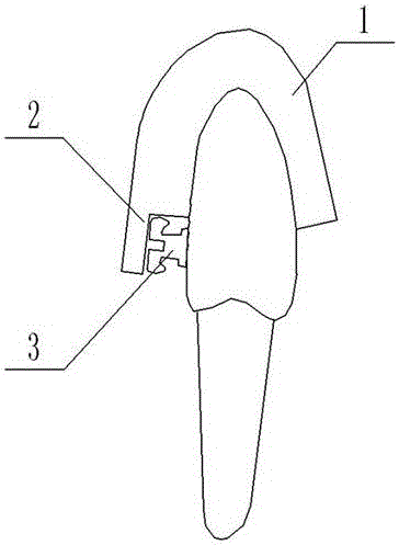
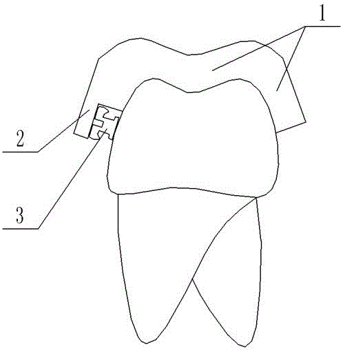
[0023] Embodiment 1: as figure 1 , figure 2 As shown, a split guide plate for precise positioning of orthodontic brackets includes an anastomotic part 1 and a buccal groove 2. The anastomotic part 1 is arranged on the crown of the tooth and surrounds the occlusal surface of the teeth, Part of the lip and buccal surface, part of the lingual surface, and coincides with the tooth body. The buccal groove 2 is located on the lip and buccal side of the anastomosis of the teeth. The inner surface of the buccal groove 2 and the orthodontic bracket 3 Occlusal side anastomosis.

[0024] The height of the buccal groove 2 is consistent with the height of the planned orthodontic bracket 3 , and the buccal groove 2 is used for accommodating and positioning the bracket. The guide plate is made individually for a single tooth, the outer side of the buccal groove 2 is open, and the guide plate is made of a transparent material.

[0025] The guide plate is a 3D printing split guide plate. ...

Embodiment 2

[0033] Embodiment 2: as figure 1 , figure 2 As shown, a split guide plate for precise positioning of orthodontic brackets includes an anastomotic part 1 and a buccal groove 2. The anastomotic part 1 is arranged on the crown of the tooth and surrounds the occlusal surface of the teeth, Part of the lip and buccal surface, part of the lingual surface, and coincides with the tooth body. The buccal groove 2 is located on the lip and buccal side of the anastomotic part 1 of the teeth. The inner surface of the buccal groove 2 and the orthodontic bracket 3 The side of the occlusal side is anastomosed.

[0034] The height of the buccal groove 2 is consistent with the height of the planned orthodontic bracket 3 , and the buccal groove 2 is used for accommodating and positioning the bracket. The guide plate is made individually for a single tooth, the outer side of the buccal groove 2 is open, and the guide plate is made of a transparent material.

[0035] The guide plate is a 3D pri...


PUM


Abstract

The invention provides a split type guide plate for accurately positioning an orthodontic bracket. The split type guide plate comprises a tooth occluding part and a buccal surface groove, wherein the tooth occluding part is arranged on a dental crown of teeth, comprises a tooth occluding surface, part of buccal labial surface and part of lingual surface and is matched with a dental body; the buccal surface groove is formed in the buccal labial side of the tooth occluding part; the inner side surface of the buccal surface groove is matched with the side surface of an occlusion part of the orthodontic bracket. The split type guide plate disclosed by the invention has the advantages that quick and one-time bonding of the orthodontic bracket can be realized; a bonding process is simple to operate; a doctor is enabled to simulate the tooth aligning condition on a computer, and then an optimal position and the direction of the bracket are designed according to a simulation result, thereby realizing an effect of inducing the alignment; the repeatable and accurate positioning of each orthodontic bracket can be realized; even if a single orthodontic bracket falls off at later stage and needs to be bonded again, the orthodontic bracket can be accurately positioned at the original position by using an original guide plate; the orthodontic bracket can be matched with brackets of various models in the market.

Description

technical field [0001] The invention relates to a guide plate, in particular to a split guide plate for precise positioning of orthodontic brackets. Background technique [0002] At present, the clinical operation of bonding orthodontic brackets is usually to place the bracket coated with adhesive directly on the tooth surface, and then fine-tune the position and direction of the bracket. The fine-tuning process not only consumes a lot of time and energy for the doctor, but also the final position and direction of the bracket depends on the doctor's personal experience, which often leads to the position and direction of the bracket not being optimal, or even very poor. In addition, during the use of orthodontic brackets, individual brackets often fall off, and it is difficult for doctors to glue the brackets back to their original proper positions. These will have adverse effects on the orthodontic treatment process. At present, the bonding of orthodontic brackets in clini...

Claims


Application Information

Patent Timeline
IPC IPC(8): A61C7/16
CPCA61C7/002A61C7/146A61C7/16
Inventor 姚洋廖文古霞王帅李宇赵志河宫苹
Owner SICHUAN UNIV
Learn More