

Bearing part automatic sorting method
A technology for automatic sorting and parts, which is used in sorting, analyzing materials, and analyzing materials by optical means. , to achieve the effect of improving detection efficiency and detection consistency, good sorting effect, and continuous detection of surface quality
- Summary
- Abstract
- Description
- Claims
- Application Information
AI Technical Summary
Problems solved by technology
Method used
Image

Examples
Embodiment Construction
[0028] Below in conjunction with accompanying drawing and embodiment, further elaborate the present invention. In the following detailed description, certain exemplary embodiments of the invention are described by way of illustration only. Needless to say, those skilled in the art would realize that the described embodiments can be modified in various different ways, all without departing from the spirit and scope of the present invention. Accordingly, the drawings and description are illustrative in nature and not intended to limit the scope of the claims.
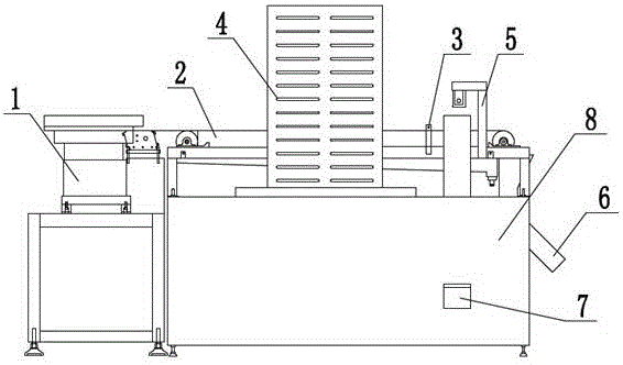
[0029] like figure 1 As shown, according to the automatic sorting method of bearing parts according to the embodiment of the present invention, the automatic sorting method of bearing parts includes the following steps:
[0030] (1) Transport the bearing parts to be tested to the detection area through the conveying device;
[0031] (2) After the bearing components to be detected are transported to the detection area, ...
PUM
 Abstract
Description
Claims
Application Information