Bending device for cable

A bending device and cable technology, applied in the field of electric power, can solve problems such as unsatisfactory use requirements, low efficiency, and low precision, and achieve the effects of simple structure, stable operation, and high bending efficiency

Inactive Publication Date: 2017-03-15
张辉海
View PDF6 Cites 0 Cited by
  • Summary
  • Abstract
  • Description
  • Claims
  • Application Information

AI Technical Summary

Problems solved by technology

Relying on manual bending is very laborious, low precision, and low efficiency, which cannot meet the needs of use

Method used


Image

  • Bending device for cable
  • Bending device for cable
  • Bending device for cable

Examples


Embodiment Construction

[0021] The present invention will be further described in detail below in conjunction with specific examples, but the implementation of the present invention is not limited thereto.

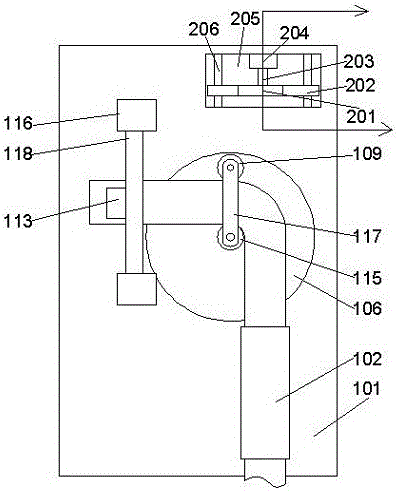
[0022] like Figure 1-5 As shown, a bending device for cables includes a frame body 101 and a feeding device and a bending device arranged above the frame body 101;

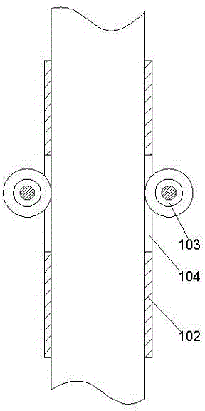
[0023] The feeding device includes a guide tube 102 fixedly installed on the frame body and transmission wheels 103 arranged on both sides of the guide tube 102, front and rear grooves 104 are arranged on both sides of the guide tube 102, the When the transmission wheel 103 rotates, its outer peripheral wall is located inside the front and rear grooves 104 of the guide tube 102;

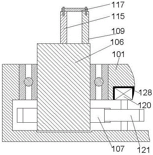
[0024] The bending device includes a circular turntable 106 arranged on the frame body 101, the circular turntable 106 is located at the rear side end of the guide tube 102, and a center is arranged in the middle of the circular turntable 106. A cylindri...


PUM


Abstract

The invention discloses a bending device for a cable. The bending device comprises a frame body, a feed device and a bending device body, wherein the feed device and the bending device body are arranged above the frame body. The feed device comprises a guide pipe fixedly mounted on the frame body and transmission wheels arranged on the two sides of the guide pipe. Front-and-back grooves are formed in the two sides of the guide pipe. When each transmission wheel rotates, the outer circumferential wall of the transmission wheel is located on the inner side of the corresponding front-and-back groove of the guide pipe. The bending device body comprises a round rotary frame arranged on the frame body. The round rotary frame is located at the rear side end of the guide pipe. A center cylindrical rod is arranged in the middle of the round rotary frame. A rotating groove is formed in the frame body. The round rotary frame is mounted in the rotating groove through a rotating bearing piece. A driven gear is mounted on the outer side of the lower portion of the round rotary frame. A driving gear matched with the driven gear is mounted on the right side of the driven gear. A bending acting piece parallel to the center cylindrical rod is arranged on the round rotary frame.

Description

technical field [0001] The invention relates to the field of electric power, in particular to a bending device for cables. Background technique [0002] In the process of construction and application of power transmission cables, it is often necessary to bend the wiring head to adapt to the shape of the specific fixed part of the power equipment, so as to securely connect the cables. Relying on manual bending is very laborious, has low precision, and is inefficient, which cannot meet the needs of use. Contents of the invention [0003] The purpose of the present invention is to provide a bending device for cables, which can improve the problems existing in the prior art, can conveniently control the bending length of cables, can realize bending work of different lengths, has high bending efficiency and high bending quality, and The qualified products after bending can be marked. [0004] The present invention is realized through the following technical solutions: [000...

Claims


Application Information

Patent Timeline
Patent Type & Authority Applications(China)
IPC IPC(8): B21F1/00B21F23/00B21C51/00
CPCB21F1/00B21C51/005B21F23/00
Inventor 张辉海
Owner 张辉海
Why Eureka
Try Eureka