Bicycle folding rear fork controlling device

A control device and bicycle technology, applied to bicycles, foldable bicycles, motor vehicles, etc., can solve the problems of cumbersome operation process, and achieve the effect of simple operation process, convenient and quick folding and unfolding

Inactive Publication Date: 2017-03-15
佛山市狮子厂科技有限公司
View PDF0 Cites 0 Cited by
  • Summary
  • Abstract
  • Description
  • Claims
  • Application Information

AI Technical Summary

Problems solved by technology

[0002] Folding bicycles are now more and more popular due to their ease of use, but the folding and unfolding of folding bicycles must be done manually, es

Method used


Image

  • Bicycle folding rear fork controlling device
  • Bicycle folding rear fork controlling device
  • Bicycle folding rear fork controlling device

Examples


Example

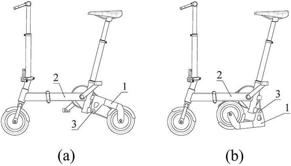
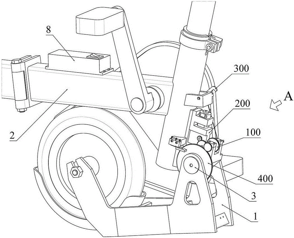
[0045] The first embodiment: as figure 2 , 3 , 4, 5, 6, 7, 8, 9, 10, a control device for a bicycle folding rear fork, comprising a rear fork 1, a front frame 2 and a first rotating shaft 3, a rear fork 1 and a front frame 2 Hinged by the first rotating shaft 3, the rear fork 1 is provided with a first limit block 11, and the front frame 2 is provided with a second limit block 21. When the rear fork 1 is in the unfolded state, the first limit block 11 and the second limit block 11 are provided. The two limit blocks 21 are in contact; the control device for the bicycle folding rear fork further includes a differential gear 100 , a driving unit 200 , a locking unit 300 and an execution unit 400 .

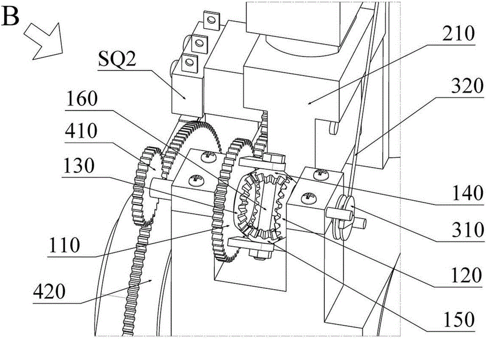
[0046] The differential 100 is mounted on the front frame 2; the differential 100 includes a differential main gear 110, a first side gear 120, a second side gear 130, planetary gears 140, 150 and a planetary gear shaft 160; the differential The gear main gear 110 is provided with ...

Example

[0059] Second embodiment: as Figure 12 and Figure 13 As shown, the difference between this embodiment and the first embodiment is that the control circuit unit 220 of the driving unit 200 is different.

[0060] In this embodiment, the control circuit unit 220 includes a first micro switch SQ1 , a second micro switch SQ2 , a first diode V1 , a second diode V2 , a bipolar double throw switch SA1 and a battery G. The double-pole double-throw switch SA1 is a non-automatic reset switch, that is, pressing the button of the switch makes the switch switch state. When the hand releases the button, the switch remains in the current state and will not automatically return to the original state; the double-pole double-throw type The switch SA1 has two sets of terminals, namely the first pole first terminal a1, the first pole second terminal a2 and the first pole common terminal a0, the second pole first terminal b1, the second pole second terminal b2 and the second pole Common termina...

Example

[0068] The third embodiment: as Figure 14 and Figure 15 As shown, the difference between this embodiment and the first embodiment is that the control circuit unit 220 of the driving unit 200 is different.

[0069] In this embodiment, the control circuit unit 220 includes a first micro switch SQ1, a second micro switch SQ2, a third relay K3, a fourth relay K4, a first button switch SB1, a second button switch SB2 and a battery G; The third relay K3 has three sets of terminals, namely the first common terminal k31 of the third relay and the first normally open terminal k32 of the third relay, the second common terminal k33 of the third relay and the second normally open terminal k34 of the third relay, the third relay The third common terminal k35 and the third normally open terminal k36 of the third relay; the fourth relay K4 has three sets of terminals, namely the first common terminal k41 of the fourth relay and the first normally open terminal k42 of the fourth relay, and...


PUM


Abstract

The invention relates to a bicycle folding rear fork controlling device. The device comprises a rear fork, a front frame, a first rotating shaft, a differential mechanism, a driving unit, a locking unit and an execution unit, wherein the rear fork is hinged with the front frame through the first rotating shaft; the driving unit is connected with the locking unit and the execution unit through the differential mechanism; the locking unit can be used for achieving the locking and unlocking between the rear fork and the front frame; and the execution unit can be used for driving the rear fork to rotate relative to the front frame. When a rider presses a switch of the driving unit, the driving unit is used for driving the locking unit and the execution unit to move through the differential mechanism, so that a bicycle folding rear fork can be folded and unfolded, the operating process is simple, and a folding bicycle can be folded and unfolded conveniently and quickly.

Description

technical field [0001] The invention relates to a control device, in particular to a control device for a folding rear fork of a bicycle. Background technique [0002] Folding bicycles are now more and more popular due to their ease of use, but the folding and unfolding of folding bicycles must be done manually, especially for bicycles whose rear forks need to be folded. The folding and unfolding of the rear forks requires manual operation. The process is more cumbersome. Contents of the invention [0003] The technical problem to be solved by the present invention is to provide a control device for a bicycle folding rear fork, which can automatically complete the folding and unfolding of the bicycle folding rear fork. [0004] In order to solve the above-mentioned technical problems, the technical solution of the present invention is: a control device for folding rear forks of bicycles, including a rear fork, a front frame and a first rotating shaft, and the rear fork an...

Claims


Application Information

Patent Timeline
IPC IPC(8): B62K15/00
CPCB62K15/006
Inventor 李穆威李穆生
Owner 佛山市狮子厂科技有限公司
Why Eureka
Try Eureka