A shock-resistant multi-directional energy-dissipating damper with extra-large tonnage
An anti-shock and damper technology, applied in bridge parts, bridges, buildings, etc., can solve the problems of not meeting the shock absorption requirements of large bridges, limited damping force tonnage, and single working direction, so as to achieve stable and reliable working performance and ensure safety. Sexual, compact effect
- Summary
- Abstract
- Description
- Claims
- Application Information
AI Technical Summary
Problems solved by technology
Method used
Image
Examples
Embodiment 1
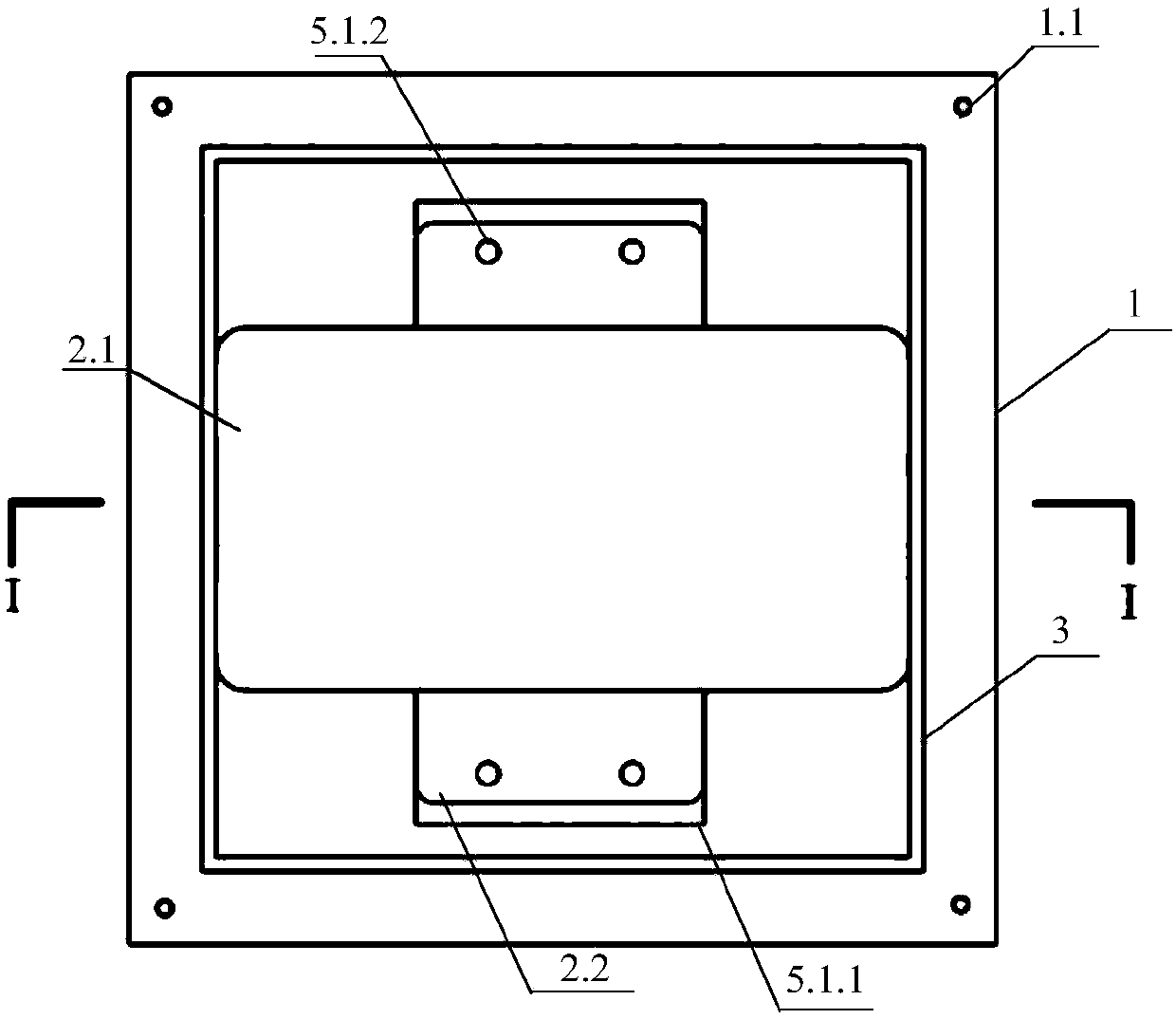
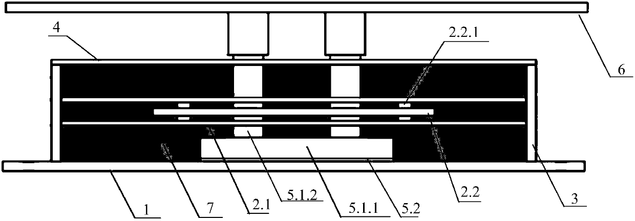
[0031] Such as figure 1 and 2 As shown in the figure, a multi-directional energy-dissipating damper capable of resisting shocks and large tonnages includes a bottom plate 1, an impedance plate 2, a side plate 3, a top plate 4, a transmission bracket 5, and an upper connecting device 6;
[0032] The bottom plate 1 is provided with a bolt through hole 1.1, the side plate 3 is welded on the bottom plate 1, and the top plate 4 is welded on the side plate 3 to form a steel box;
[0033] The steel box is provided with an impedance plate 2 and a transmission bracket 5, and the internal space of the steel box is filled with viscous liquid 7;
[0034] The transmission bracket 5 is composed of a steel frame 5.1 and a polytetrafluoroethylene plate 5.2, the steel frame 5.1 is composed of a steel supporting plate 5.1.1 and a steel column 5.1.2, and the polytetrafluoroethylene plate 5.2 is arranged on the bottom plate 1 , the steel supporting plate 5.1.1 is set on the polytetrafluoroethyl...
Embodiment 2
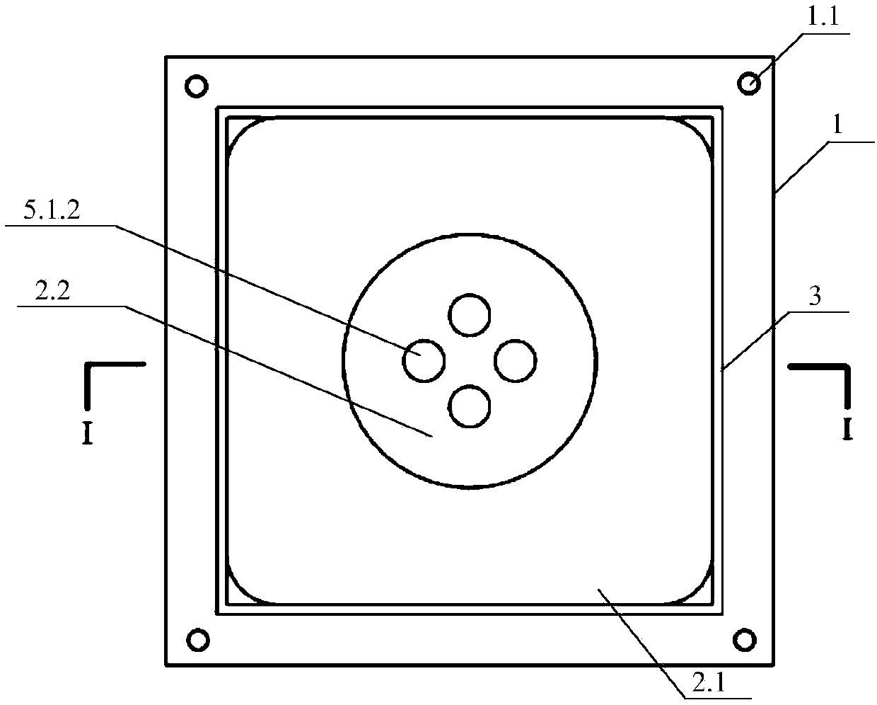
[0038] Such as image 3 and 4 As shown, the differences between this embodiment and Embodiment 1 are:
[0039] The fixed impedance plates 2.1 and the movable impedance plates 2.2 are alternately arranged vertically to form a two-layer structure.
[0040] The fixed impedance plate 2.1 is configured as a rectangle, and the movable impedance plate 2.2 is configured as a circle.
[0041] The steel frame 5.1 includes a steel supporting plate 5.1.1 and a steel column 5.1.2, and the steel column 5.1.2 is located at the center of the steel supporting plate 5.1.1.
Embodiment 3
[0043] Such as Figure 5 and 6 As shown, the differences between this embodiment and Embodiment 1 are:
[0044] The fixed impedance plate 2.1 is configured as a rectangle, and the movable impedance plate 2.2 is configured as a circle.
[0045] The steel frame 5.1 includes a steel supporting plate 5.1.1 and a steel column 5.1.2, and the steel column 5.1.2 is located at the center of the steel supporting plate 5.1.1.
PUM
 Abstract
Description
Claims
Application Information
 - R&D
- Intellectual Property
- Life Sciences
- Materials
- Tech Scout
- Unparalleled Data Quality
- Higher Quality Content
- 60% Fewer Hallucinations
Browse by: Latest US Patents, China's latest patents, Technical Efficacy Thesaurus, Application Domain, Technology Topic, Popular Technical Reports.
© 2025 PatSnap. All rights reserved.Legal|Privacy policy|Modern Slavery Act Transparency Statement|Sitemap|About US| Contact US: help@patsnap.com


