A high-efficiency and energy-saving ventilation fan

A high-efficiency energy-saving ventilation fan technology, applied in the electronic field, can solve the problems of high energy consumption and poor ventilation effect of the ventilation fan, and achieve the effect of saving electric energy and good ventilation effect

Active Publication Date: 2019-05-28
GUANGXI UNIV
View PDF10 Cites 0 Cited by
  • Summary
  • Abstract
  • Description
  • Claims
  • Application Information

AI Technical Summary

Problems solved by technology

[0003] The purpose of the present invention is to provide a high-efficiency and energy-saving ventilation fan to solve the problems of high energy consumption and poor ventilation effect of existing ventilation fans

Method used


Image

  • A high-efficiency and energy-saving ventilation fan

Examples


Embodiment Construction

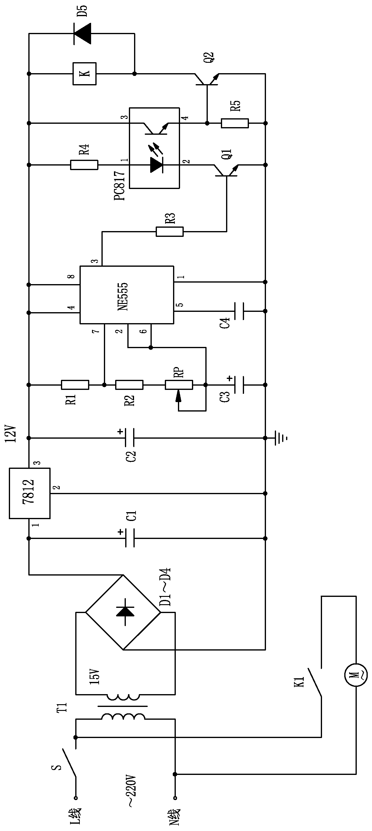
[0009] The present invention will be further described below in conjunction with the accompanying drawings.

[0010] Such as figure 1 As shown, the high-efficiency and energy-saving ventilating fan of the present invention uses the time-base circuit NE555 chip as the control core to construct the circuit. The circuit adopts 220V mains power through transformer T1 to transform and rectify bridge D1-D4 full-wave rectification, and then through capacitor C1 in turn. Filtering, three-terminal voltage regulator 7812 voltage stabilization, after filtering by capacitor C2, DC 12V power supply is obtained for power supply; pin 4 and pin 8 of NE555 chip are connected to 12V power supply, pin 7 is connected to one end of resistors R1 and R2, and the other end of resistor R1 Connect the 12V power supply, the other end of the resistor R2 is connected to one end of the adjustable resistor RP, the other end of the adjustable resistor RP and the adjustment end are connected to pins 2 and 6 o...


PUM


Abstract

The invention provides a high-efficiency and energy-saving ventilation fan. A circuit of the high-efficiency and energy-saving ventilation fan uses a time-base circuit NE555 chip as a control core to be constructed, compared with the continuous work of the ordinary ventilation fan, the ventilation fan disclosed by the invention uses an intermittent working mode while working to save electric energy, and further make exchanged fresh air be fully mixed and replaced with dirty air in indoor corners when the ventilation fan stops, so that the dirty air in the indoor corners can be effectively discharged when the ventilation fan is started again to achieve an ideal ventilation effect, and the high-efficiency and energy-saving ventilation fan is better in ventilation effect compared with the conventional ventilation fan.

Description

technical field [0001] The invention relates to a ventilating fan, in particular to a high-efficiency and energy-saving ventilating fan, which belongs to the field of electronic technology. Background technique [0002] A ventilation fan is an air-conditioning appliance that is driven by a motor to rotate the fan blades to drive the airflow to exchange indoor and outdoor air. The purpose of ventilation is to remove indoor dirty air, adjust temperature, humidity and sensory effects, therefore, ventilation fans are widely used in homes and public places. At present, the ventilating fans on the market generally continue to work after they are turned on. However, such a working method not only wastes electric energy, but also fails to achieve the ideal ventilation effect. Because when the ventilation fan is working continuously, the fresh air exchanged in the air duct is often too late to fully mix and replace with the dirty air in the room, and is immediately discharged along ...

Claims


Application Information

Patent Timeline
Patent Type & Authority Patents(China)
IPC IPC(8): F04D25/08F04D27/00
CPCF04D25/08F04D27/00
Inventor 黄玲玲
Owner GUANGXI UNIV
Why Eureka
Try Eureka