Vertical loading testing device for integral ring tunnel structure

A tunnel structure, vertical loading technology, applied in the testing, measuring devices, instruments, etc. of machines/structural components, which can solve the problem of the incompetence of the loading device

Inactive Publication Date: 2017-03-15
TONGJI UNIV
View PDF11 Cites 16 Cited by
  • Summary
  • Abstract
  • Description
  • Claims
  • Application Information

AI Technical Summary

Problems solved by technology

[0004] Chinese patent CN 203465148 U discloses a test loading device for the whole ring structure of tunnel lining, including a central reaction force device, multiple sets of loading points uniformly distributed radially along the central reaction force device and connected to the center reaction force device, each set of loading points Radially from outside to inside, it includes load distribution beam, hydraulic device, load-bearing beam and at least one tie rod. The load distribution beam and the corresponding tie rods of the load-holding beam are respectively provided with installation holes, and the tie rod passes through the load distribution beam and the load-bearing beam. Fixed on the central reaction device, the lining ring test piece is arranged radially inside the load-bearing beam 6, and the hydraulic device is installed between the load distribution beam and the load-bearing beam to provide load, but the patented loading device is still mainly for horizontal loading , that is, the tunnel lining in the test is placed horizontally, while the actual tunnel lining is vertical
Using horizontal loading, starting from the load structure method, it can simulate the external load of the structure, but it is symmetrically arranged, that is, the load and distribution of the upper and lower sides of the structure are symmetrical and the same, but the actual upper and lower loads of the tunnel lining structure and its distribution is asymmetrical, this device cannot solve the above problems; in addition, starting from the ground structure method that can better reflect the actual force of the structure, the existing loading device is not competent

Method used


Image

  • Vertical loading testing device for integral ring tunnel structure
  • Vertical loading testing device for integral ring tunnel structure

Examples


Embodiment 1

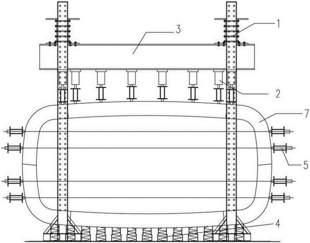
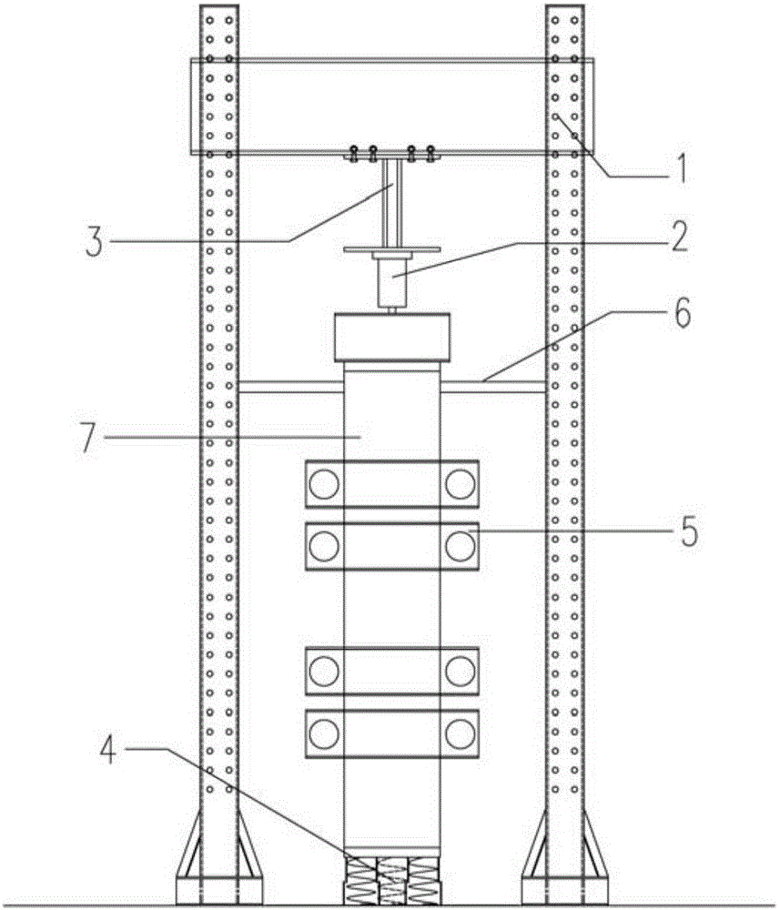
[0023] The vertical loading test device for the whole-ring tunnel structure includes a reaction frame composed of columns 1 and beams 3. The base of the reaction frame is provided with a spring support group 4, and the whole-ring tunnel structure is placed on the spring support group 4. 7. A number of jacks 2 are provided on the lower part of the beam 3. The upper ends of the jacks 2 are fixed on the beam 3, and the lower ends of the jacks are placed on the loading points on the whole-ring tunnel structure 7. Lateral loading components 5 are arranged on the left and right sides of the whole-ring tunnel structure 7. The lateral loading assembly 5 is left-right symmetrical. The lateral loading assembly 5 is composed of multiple sets of symmetrical tension self-balancing system loading devices, which are evenly distributed along the height direction of the entire ring tunnel structure. The tensioning self-balancing system loading devices include left and right loading beams, jacks,...


PUM


Abstract

The invention relates to a vertical loading testing device for integral ring tunnel structure, comprising a reaction frame composed of a column and a cross beam; a spring support group is arranged on the base of the reaction frame; an integral ring tunnel structure is placed on the spring support group; the lower part of the cross beam is provided with a jack; the upper end of the jack is fixed on the cross beam and the lower end abuts against the loading point of the integral ring tunnel structure; the left side and the right side of the integral ring tunnel structure are provided with a lateral loading component each. When a test is performed, the jack and the spring support group act together to exert vertical force for vertical loading and the lateral loading components exert lateral force for lateral loading. Compared with the prior art, the invention adopts a vertical loading method to perform a test on an integral ring tunnel structure, fully takes into account of the gravity effect of the structure, and places the integral ring tunnel structure on the spring support group to simulate the boundary conditions of an elastic foundation so that the testing results truly reflect the force exerted state of a tunnel structure in a soil layer.

Description

technical field [0001] The invention relates to a test device, in particular to a vertical loading test device for a full-ring tunnel structure. Background technique [0002] In the construction and construction of tunnels, special rock and soil foundations such as soft clay foundations, expansive soil foundations, and collapsible loess foundations are often encountered. It is necessary to carry out research on the bearing deformation characteristics of the foundation, and it is necessary to perform mechanical performance tests on the structural equipment in the tunnel. Ensure the safety of tunnel construction. The traditional tunnel structure test adopts the horizontal loading method, and loads through the symmetrical tension self-balancing system to test the mechanical properties of the tunnel structure. However, this method cannot consider the gravity effect of the structure, nor does it consider the impact of soil compression deformation. The distortion of the boundary ...

Claims


Application Information

Patent Timeline
Patent Type & Authority Applications(China)
IPC IPC(8): G01M99/00
CPCG01M99/007
Inventor 柳献蒋首超梁霄
Owner TONGJI UNIV
Why Eureka
Try Eureka